A29040BL-70F AMIC, A29040BL-70F Datasheet - Page 13
A29040BL-70F
Manufacturer Part Number
A29040BL-70F
Description
IC, SM, FLASH, 4MB, 5V
Manufacturer
AMIC
Datasheet
1.A29040BL-70F.pdf
(29 pages)
Specifications of A29040BL-70F
Memory Size
4Mbit
Supply Voltage Range
4.5V To 5.5V
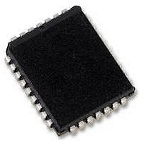
Memory Case Style
PLCC
No. Of Pins
32
Access Time
70ns
Interface
Parallel
Logic Function Number
29040
Memory Configuration
512K X
Package / Case
PLCC
Memory Type
Uniform Sector Flash
Operating Temperature Range
0°C To +70°C
Rohs Compliant
Yes
Lead Free Status / RoHS Status
Lead free / RoHS Compliant
Available stocks
Company
Part Number
Manufacturer
Quantity
Price
Company:

Part Number:
A29040BL-70F
Manufacturer:
INTERSIL
Quantity:
140
Part Number:
A29040BL-70F
Manufacturer:
AMIC
Quantity:
20 000


I/O
Toggle Bit I on I/O
or Erase algorithm is in progress or complete, or whether the
device has entered the Erase Suspend mode. Toggle Bit I
may be read at any address, and is valid after the rising edge
of the final
the program or erase operation), and during the sector erase
time-out.
During an Embedded Program or Erase algorithm operation,
successive read cycles to any address cause I/O
(The system may use either
cycles.) When the operation is complete, I/O
After an erase command sequence is written, if all sectors
selected for erasing are protected, I/O
approximately 100µs, then returns to reading array data. If
not all selected sectors are protected, the Embedded Erase
algorithm erases the unprotected sectors, and ignores the
selected sectors that are protected.
The system can use I/O
whether a sector is actively erasing or is erase-suspended.
When the device is actively erasing (that is, the Embedded
Erase algorithm is in progress), I/O
device enters the Erase Suspend mode, I/O
However, the system must also use I/O
sectors are erasing or erase-suspended. Alternatively, the
system can use I/O
Polling").
If a program address falls within a protected sector, I/O
toggles for approximately 2µs after the program command
sequence is written, then returns to reading array data.
I/O
and stops toggling once the Embedded Program algorithm is
complete.
The Write Operation Status table shows the outputs for
Toggle Bit I on I/O
algorithm, and to the Toggle Bit Timings figure in the "AC
Characteristics" section for the timing diagram. The I/O
I/O
graphical form. See also the subsection on " I/O
II".
I/O
The "Toggle Bit II" on I/O
whether a particular sector is actively erasing (that is, the
Embedded Erase algorithm is in progress), or whether that
sector is erase-suspended. Toggle Bit II is valid after the
rising edge of the final
sequence.
I/O
those sectors that have been selected for erasure. (The
system may use either
cycles.) But I/O
actively erasing or is erase-suspended. I/O
indicates whether the device is actively erasing, or is in
Erase Suspend, but cannot distinguish which sectors are
selected for erasure. Thus, both status bits are required for
sector and mode information. Refer to Table 5 to compare
outputs for I/O
Figure 4 shows the toggle bit algorithm in flowchart form, and
the section " I/O
also the " I/O
Bit Timings figure for the toggle bit timing diagram. The I/O
(January, 2007, Version 1.0)
6
6
2
6
2
: Toggle Bit I
: Toggle Bit II
also toggles during the erase-suspend-program mode,
figure shows the differences between I/O
toggles when the system reads at addresses within
WE
6
2
: Toggle Bit I" subsection. Refer to the Toggle
and I/O
2
2
: Toggle Bit II" explains the algorithm. See
pulse in the command sequence (prior to
6
cannot distinguish whether the sector is
indicates whether an Embedded Program
7
6
. Refer to Figure 4 for the toggle bit
(see the subsection on " I/O
6
.
6
OE
2
, when used with I/O
and I/O
WE
OE
or
or
pulse in the command
CE
2
CE
together to determine
6
2
to control the read
toggles. When the
to determine which
to control the read
6
6
, by comparison,
6
stops toggling.
6
stops toggling.
2
2
toggles for
: Toggle Bit
and I/O
6
6
, indicates
to toggle.
7
:
Data
2
6
vs.
in
6
2
12
vs. I/O
graphical form.
Reading Toggle Bits I/O
Refer to Figure 4 for the following discussion. Whenever the
system initially begins reading toggle bit status, it must read
I/O
toggle bit is toggling. Typically, a system would note and
store the value of the toggle bit after the first read. After the
second read, the system would compare the new value of
the toggle bit with the first. If the toggle bit is not toggling, the
device has completed the program or erase operation. The
system can read array data on I/O
read cycle.
However, if after the initial two read cycles, the system
determines that the toggle bit is still toggling, the system also
should note whether the value of I/O
on I/O
whether the toggle bit is toggling, since the toggle bit may
have stopped toggling just as I/O
is no longer toggling, the device has successfully completed
the program or erase operation. If it is still toggling, the
device did not complete the operation successfully, and the
system must write the reset command to return to reading
array data.
The remaining scenario is that the system initially determines
that the toggle bit is toggling and I/O
system may continue to monitor the toggle bit and I/O
through successive read cycles, determining the status as
described in the previous paragraph. Alternatively, it may
choose to perform other system tasks. In this case, the
system must start at the beginning of the algorithm when it
returns to determine the status of the operation (top of Figure
4).
I/O
I/O
exceeded a specified internal pulse count limit. Under these
conditions I/O
indicates the program or erase cycle was not successfully
completed.
The I/O
program a "1 "to a location that is previously programmed to
"0." Only an erase operation can change a "0" back to a "1."
Under this condition, the device halts the operation, and
when the operation has exceeded the timing limits, I/O
produces a "1."
Under both these conditions, the system must issue the reset
command to return the device to reading array data.
I/O
After writing a sector erase command sequence, the system
may read I/O
operation has begun. (The sector erase timer does not apply
to the chip erase command.) If additional sectors are
selected for erasure, the entire time-out also applies after
each additional sector erase command. When the time-out is
complete, I/O
ignore I/O
additional sector erase commands will always be less than
50µs. See also the "Sector Erase Command Sequence"
section.
7
5
5
3
: Exceeded Timing Limits
: Sector Erase Timer
- I/O
indicates whether the program or erase time has
6
5
). If it is, the system should then determine again
5
figure shows the differences between I/O
failure condition may appear if the system tries to
0
3
if the system can guarantee that the time between
at least twice in a row to determine whether a
5
3
3
produces a "1." This is a failure condition that
switches from "0" to "1." The system may
to determine whether or not an erase
AMIC Technology, Corp.
6
, I/O
5
2
went high. If the toggle bit
A29040B Series
7
5
5
is high (see the section
has not gone high. The
- I/O
0
on the following
2
and I/O
6
in
5
5
Related parts for A29040BL-70F
Image
Part Number
Description
Manufacturer
Datasheet
Request
R


Part Number:
Description:
512K X 8 Bit CMOS 5.0 Volt-only, Uniform Sector Flash Memory
Manufacturer:
AMICC [AMIC Technology]
Datasheet:
Part Number:
Description:
2m X 16 Bit X 4 Banks Synchronous Dram - Amic Technology
Manufacturer:
AMIC Technology Corporation
Datasheet:

Part Number:
Description:
58T1324
Manufacturer:
AMIC
Datasheet:
Part Number:
Description:
Manufacturer:
AMIC Technology Corporation
Datasheet:
Part Number:
Description:
Manufacturer:
AMIC Technology Corporation
Datasheet:
Part Number:
Description:
Manufacturer:
AMIC Technology Corporation
Datasheet:
Part Number:
Description:
Manufacturer:
AMIC Technology Corporation
Datasheet:
Part Number:
Description:
Manufacturer:
AMIC Technology Corporation
Datasheet:
Part Number:
Description:
Manufacturer:
AMIC Technology Corporation
Datasheet:
Part Number:
Description:
Manufacturer:
AMIC Technology Corporation
Datasheet:
Part Number:
Description:
Manufacturer:
AMIC Technology Corporation
Datasheet:
Part Number:
Description:
Manufacturer:
AMIC Technology Corporation
Datasheet:
Part Number:
Description:
Manufacturer:
AMIC Technology Corporation
Datasheet:
Part Number:
Description:
Manufacturer:
AMIC Technology Corporation
Datasheet: