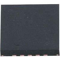
LTC4160EUDC-1#PBF Linear Technology, LTC4160EUDC-1#PBF Datasheet - Page 20

LTC4160EUDC-1#PBF
Manufacturer Part Number
LTC4160EUDC-1#PBF
Description
IC, BATT CHRG, Li-Ion, Li-Polymer, 1.2A, QFN20
Manufacturer
Linear Technology
Datasheet
1.LTC4160EUDC-1PBF.pdf
(32 pages)
Specifications of LTC4160EUDC-1#PBF
Battery Type
Li-Ion, Li-Polymer
Input Voltage
5.5V
Battery Charge Voltage
4.1V
Charge Current Max
1.2A
Battery Ic Case Style
QFN
No. Of Pins
20
No. Of Series Cells
1
Rohs Compliant
Yes
Lead Free Status / RoHS Status
Lead free / RoHS Compliant
Lead Free Status / RoHS Status
Lead free / RoHS Compliant
Available stocks
Company
Part Number
Manufacturer
Quantity
Price
OPERATION
LTC4160/LTC4160-1
switching regulator is in On-The-Go mode. When a short
circuit condition is detected, FAULT will go low-Z. The
ENOTG or VBUSGD pins can be used to determine which
fault has occurred. If ENOTG or VBUSGD is low when FAULT
went low, then a bad battery fault has occurred. If either
pin is high, then a short circuit on V
NTC Thermistor
The battery temperature is measured by placing a nega-
tive temperature coefficient (NTC) thermistor close to the
battery pack.
To use this feature connect the NTC thermistor, R
tween the NTC pin and ground and a bias resistor, R
from NTCBIAS to NTC. R
resistor with a value equal to the value of the chosen NTC
thermistor at 25°C (R25).
The LTC4160/LTC4160-1 will pause charging when the
resistance of the NTC thermistor drops to 0.54 times the
value of R25 or approximately 54k for a 100k thermis-
tor. For a Vishay Curve 1 thermistor, this corresponds to
approximately 40°C. If the battery charger is in constant-
voltage (float) mode, the safety timer also pauses until the
thermistor indicates a return to a valid temperature. As the
temperature drops, the resistance of the NTC thermistor
rises. The LTC4160/LTC4160-1 are also designed to pause
charging when the value of the NTC thermistor increases
to 3.25 times the value of R25. For a Vishay Curve 1
100k thermistor, this resistance, 325k, corresponds to
approximately 0°C. The hot and cold comparators each
have approximately 3°C of hysteresis to prevent oscilla-
tion about the trip point. Grounding the NTC pin disables
all NTC functionality.
Thermal Regulation
To prevent thermal damage to the LTC4160/LTC4160-1 or
surrounding components, an internal thermal feedback
loop will automatically decrease the programmed charge
current if the die temperature rises to 105°C. This thermal
regulation technique protects the LTC4160/LTC4160-1
from excessive temperature due to high power operation
or high ambient thermal conditions, and allows the user
to push the limits of the power handling capability with
20
NOM
should be a 1% 200ppm
BUS
has occurred.
NTC
NOM
, be-
,
a given circuit board design. The benefit of the LTC4160/
LTC4160-1 thermal regulation loop is that charge current
can be set according to actual conditions rather than
worst-case conditions for a given application with the
assurance that the charger will automatically reduce the
current in worst-case conditions.
Overvoltage Protection
The LTC4160/LTC4160-1 can protect themselves from the
inadvertent application of excessive voltage to V
just two external components: an N-channel MOSFET and
a 6.2k resistor. The maximum safe overvoltage magnitude
will be determined by the choice of the external MOSFET
and its associated drain breakdown voltage.
The overvoltage protection circuit consists of two pins.
The first, OVSENS, is used to measure the externally ap-
plied voltage through an external resistor. The second,
OVGATE, is an output used to drive the gate pin of the
external MOSFET. When OVSENS is below 6V, an inter-
nal charge pump will drive OVGATE to approximately
1.88 • OVSENS. This will enhance the N-channel MOSFET
and provide a low impedance connection to V
will, in turn, power the LTC4160/LTC4160-1. If OVSENS
should rise above 6V due to a fault or the use of an in-
correct wall adapter, OVGATE will be pulled to GND. This
disables the external MOSFET and protects downstream
circuitry. When the voltage drops below 6V again, the
external MOSFET will be re-enabled.
The charge pump output on OVGATE has limited output
drive capability. Care must be taken to avoid leakage on
this pin as it may adversely affect operation.
See the Applications Information section for resistor power
dissipation rating calculations, a table of recommended
components, and reverse-voltage protection.
Shutdown Mode
The USB switching regulator is enabled whenever V
above V
suspend mode.
The ideal diode(s) are enabled at all times and cannot be
disabled.
UVLO
and the LTC4160/LTC4160-1 are not in USB
BUS
BUS
which
BUS
41601fa
with
is


