AIS326DQ STMicroelectronics, AIS326DQ Datasheet - Page 47
AIS326DQ
Manufacturer Part Number
AIS326DQ
Description
IC ACCELEROMETER 3-AXIS 28-QFN
Manufacturer
STMicroelectronics
Datasheet
1.AIS326DQ.pdf
(51 pages)
Specifications of AIS326DQ
Axis
X, Y, Z
Acceleration Range
±2g, 6g
Sensitivity
1024LSB/g, 340LSB/g
Voltage - Supply
3 V ~ 3.6 V
Output Type
Digital
Bandwidth
40Hz ~ 2.56kHz Selectable
Interface
SPI
Mounting Type
Surface Mount
Package / Case
28-QFN
Sensing Axis
X, Y, Z
Acceleration
2 g, 6 g
Digital Output - Number Of Bits
12 bit
Supply Voltage (max)
3.6 V
Supply Voltage (min)
3 V
Supply Current
0.67 mA
Maximum Operating Temperature
+ 105 C
Minimum Operating Temperature
- 40 C
Digital Output - Bus Interface
SPI
Mounting Style
SMD/SMT
Shutdown
Yes
Operating Supply Voltage (min)
3V
Operating Supply Voltage (typ)
3.3V
Operating Supply Voltage (max)
3.6V
Operating Temperature (min)
-40C
Operating Temperature (max)
105C
Operating Temperature Classification
Industrial
Product Depth (mm)
7mm
Product Length (mm)
7mm
Mounting
Surface Mount
Pin Count
28
Lead Free Status / RoHS Status
Lead free / RoHS Compliant
Available stocks
Company
Part Number
Manufacturer
Quantity
Price

Part Number:
AIS326DQ
Manufacturer:
ST
Quantity:
20 000


AIS326DQ
9.2.1
9.3
PCB design rules
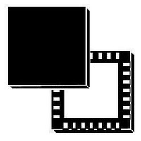
Figure 45. Recommended land and solder mask design for QFPN packages
A = Clearance from PCB land edge to solder mask opening ≤ 0.1 mm to ensure that some
solder mask remains between PCB pads
B = PCB land length = QFPN solder pad length + 0.1 mm
C = PCB land width = QFPN solder pad width + 0.1 mm
D = PCB thermal pad solder mask opening = QFPN thermal pad side + 0.2 mm
Stencil design and solder paste application
The thickness and the pattern of the soldering paste are important for the proper
accelerometer mounting process.
●
●
●
●
●
●
●
Stainless steel stencils are recommended for solder paste application
A stencil thickness of 125 - 150 µm (5 - 6 mils) is recommended for screen printing
The final thickness of soldering paste should allow proper cleaning of flux residuals and
clearance between sensor package and PCB
Stencil aperture should have rectangular shape with dimension up to 25 µm (1mil)
smaller than PCB land
The openings of the stencil for the signal pads should be between 50% and 80% of the
PCB pad area
Optionally, for better solder paste release, the aperture walls should be trapezoidal and
the corners rounded
The fine pitch of the IC leads requires accurate alignment of the stencil to the printed
circuit board. The stencil and printed circuit assembly should be aligned to within 25 µm
(1 mil) prior to application of the solder paste.
A
Doc ID 14956 Rev 4
D
B
PACKAGE FOOTPRINT
PCB LAND
SOLDER MASK OPENING
PCB THERMAL PAD NOT TO
BE DESIGNED ON PCB
PCB THERMAL PAD SOLDER
MASK OPENING SUGGESTED
TO INCREASE DEVICE
THERMAL PAD TO PCB
CLEARANCE
C
Soldering information
47/51
Related parts for AIS326DQ
Image
Part Number
Description
Manufacturer
Datasheet
Request
R

Part Number:
Description:
STMicroelectronics [RIPPLE-CARRY BINARY COUNTER/DIVIDERS]
Manufacturer:
STMicroelectronics
Datasheet:
Part Number:
Description:
STMicroelectronics [LIQUID-CRYSTAL DISPLAY DRIVERS]
Manufacturer:
STMicroelectronics
Datasheet:

Part Number:
Description:
BOARD EVAL FOR MEMS SENSORS
Manufacturer:
STMicroelectronics
Datasheet:
Part Number:
Description:
NPN TRANSISTOR POWER MODULE
Manufacturer:
STMicroelectronics
Datasheet:
Part Number:
Description:
TURBOSWITCH ULTRA-FAST HIGH VOLTAGE DIODE
Manufacturer:
STMicroelectronics
Datasheet:
Part Number:
Description:
Manufacturer:
STMicroelectronics
Datasheet:
Part Number:
Description:
DIODE / SCR MODULE
Manufacturer:
STMicroelectronics
Datasheet:
Part Number:
Description:
DIODE / SCR MODULE
Manufacturer:
STMicroelectronics
Datasheet:
Part Number:
Description:
Search -----> STE16N100
Manufacturer:
STMicroelectronics
Datasheet:
Part Number:
Description:
Search ---> STE53NA50
Manufacturer:
STMicroelectronics
Datasheet:
Part Number:
Description:
NPN Transistor Power Module
Manufacturer:
STMicroelectronics
Datasheet:
Part Number:
Description:
DIODE / SCR MODULE
Manufacturer:
STMicroelectronics
Datasheet: