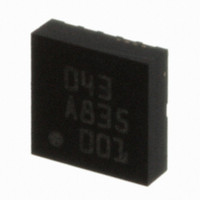
BMA150 Bosch Sensortec, BMA150 Datasheet - Page 52

BMA150
Manufacturer Part Number
BMA150
Description
3-AXIS ACCELEROMETER DIGITAL I/F
Manufacturer
Bosch Sensortec
Specifications of BMA150
Axis
X, Y, Z
Acceleration Range
± 2g, 4g, 8g
Sensitivity
256LSB/g, 128LSB/g, 64LSB/g
Voltage - Supply
2.4 V ~ 3.6 V
Output Type
Digital
Bandwidth
3kHz
Interface
I²C, SPI
Mounting Type
Surface Mount
Package / Case
12-LGA
For Use With
DM180021 - KIT STARTER MPLAB FOR PIC18F MCU828-1013 - BMA150 TRIBOX DEMO BOARD W/USB828-1009 - BMA150 DAUGHTERCARD FOR DEV KIT
Lead Free Status / RoHS Status
Lead free / RoHS Compliant
Other names
0273 141 043
828-1003-2
828-1003-2
Available stocks
Company
Part Number
Manufacturer
Quantity
Price
Company:
Part Number:
BMA150
Manufacturer:
BOSCH
Quantity:
5 888
Part Number:
BMA150
Manufacturer:
BOSCH/博世
Quantity:
20 000
Data sheet
BMA150
Bosch Sensortec
Triaxial, digital acceleration sensor
9. Internal logic functions
The sensor IC can inform the host system about specific conditions (e.g. new data ready flag or
acceleration thresholds passed) by setting an interrupt pin high even if interface communication
is not taking place. This feature can be used as “freefall indicator”, “wake-up” or “data ready
flag” for instance.
The interrupt performance can be programmed by means of control bits. Thus the criteria to
identify a special event can be tailored to a customer’s application and the sensor IC output can
be defined specifically.
9.1 Freefall logic
For freefall detection the absolute value of the acceleration data of all axes are investigated
(global criteria). A freefall situation is likely to occur when all axes fall below a lower threshold
value (“LG_thres”). The interrupt pin will be raised high if the threshold is passed for a minimum
duration. The duration time can be programmed in units of ms (max. 255ms).
The function “Freefall Interrupt” can be switched on/off by a control bit which is located within
the image of the non-volatile memory. Thus this functionality can be stored as default setting of
the sensor IC (EEPROM) but can also rapidly be changed within the image.
The reset of the freefall interrupt can be accomplished by means of a master reset of the
interrupt flag (latched interrupt) or the reset can be triggered by the acceleration signal itself
(validation of a programmable “hysteresis”).
See also section 3.2.7.
9.2 High-g logic
For indicating high-g events an upper threshold can be programmed. This logic can also be
activated by a control bit. Threshold, duration and reset behaviour can be programmed. The
high-g and freefall criteria can be logically combined with an <OR>.
See also section 3.2.8.
Rev. 1.6
Page 52
30 October 2008
© Bosch Sensortec GmbH reserves all rights even in the event of industrial property rights. We reserve all rights of disposal such
as copying and passing on to third parties. BOSCH and the symbol are registered trademarks of Robert Bosch GmbH, Germany.
Note: Specifications within this document are subject to change without notice.


