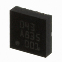
BMA150 Bosch Sensortec, BMA150 Datasheet - Page 21

BMA150
Manufacturer Part Number
BMA150
Description
3-AXIS ACCELEROMETER DIGITAL I/F
Manufacturer
Bosch Sensortec
Specifications of BMA150
Axis
X, Y, Z
Acceleration Range
± 2g, 4g, 8g
Sensitivity
256LSB/g, 128LSB/g, 64LSB/g
Voltage - Supply
2.4 V ~ 3.6 V
Output Type
Digital
Bandwidth
3kHz
Interface
I²C, SPI
Mounting Type
Surface Mount
Package / Case
12-LGA
For Use With
DM180021 - KIT STARTER MPLAB FOR PIC18F MCU828-1013 - BMA150 TRIBOX DEMO BOARD W/USB828-1009 - BMA150 DAUGHTERCARD FOR DEV KIT
Lead Free Status / RoHS Status
Lead free / RoHS Compliant
Other names
0273 141 043
828-1003-2
828-1003-2
Available stocks
Company
Part Number
Manufacturer
Quantity
Price
Company:
Part Number:
BMA150
Manufacturer:
BOSCH
Quantity:
5 888
Part Number:
BMA150
Manufacturer:
BOSCH/博世
Quantity:
20 000
Data sheet
BMA150
Bosch Sensortec
Triaxial, digital acceleration sensor
3.3.4 Selftest_0
The self-test command (address 0Ah, bit 2) uses electrostatic forces to move the MEMS
common electrode. The result from selftest can be verified by reading st_result (section 3.4.1).
During selftest procedurno external change of the acceleration should be generated.
3.3.5 Selftest_1
This self test bit (address 0Ah, bit3) does not generate any electrostatic force in the MEMS
element but is used to verify the interrupt function is working correctly and that microprocessor
is able to react to the interrupts.
0g acceleration is emulated at ADC input and the user can detect the whole logic path for
interrupt, including the PCB path integrity. The LG_thres register must be set to about 0.4g
while LG_dur = 0 to generate a low-g interrupt
3.3.6 Soft_reset
BMA150 is reset each time this bit (address 0Ah, bit 1) is written to 1. The effect is identical to
power-on reset. Control, status and image registers are reset to values stored in the EEPROM.
After soft_reset or power-on reset BMA150 comes up in normal mode or wake-up mode. It is
not possible to boot BMA150 to sleep mode.
No serial transaction should occur within 10us after soft_reset command.
The soft_reset procedure may overwrite the SPI4 setting (section 3.1.1). Thus the correct
interface configuration may have to be updated.
3.3.7 Sleep
This bit (address 0Ah, bit 0) turns the sensor IC in sleep mode. Control and image registers are
not cleared.
When BMA150 is in sleep mode no operation can be performed but wake-up the sensor IC by
setting sleep=0 or soft_reset. As a consequence all write and read operations are forbidden
when the sensor IC is in sleep mode except command used to wake up the device or soft_reset
command. After sleep mode removal, it takes 1ms to obtain stable acceleration values (>99%
data integrity). User must wait for 10ms before first EEPROM write. For the same reason,
BMA150 must not be turned in sleep mode when any update_image, self_test or EEPROM
write procedure is on going.
Rev. 1.6
Page 21
30 October 2008
© Bosch Sensortec GmbH reserves all rights even in the event of industrial property rights. We reserve all rights of disposal such
as copying and passing on to third parties. BOSCH and the symbol are registered trademarks of Robert Bosch GmbH, Germany.
Note: Specifications within this document are subject to change without notice.


