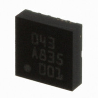
BMA150 Bosch Sensortec, BMA150 Datasheet - Page 11

BMA150
Manufacturer Part Number
BMA150
Description
3-AXIS ACCELEROMETER DIGITAL I/F
Manufacturer
Bosch Sensortec
Specifications of BMA150
Axis
X, Y, Z
Acceleration Range
± 2g, 4g, 8g
Sensitivity
256LSB/g, 128LSB/g, 64LSB/g
Voltage - Supply
2.4 V ~ 3.6 V
Output Type
Digital
Bandwidth
3kHz
Interface
I²C, SPI
Mounting Type
Surface Mount
Package / Case
12-LGA
For Use With
DM180021 - KIT STARTER MPLAB FOR PIC18F MCU828-1013 - BMA150 TRIBOX DEMO BOARD W/USB828-1009 - BMA150 DAUGHTERCARD FOR DEV KIT
Lead Free Status / RoHS Status
Lead free / RoHS Compliant
Other names
0273 141 043
828-1003-2
828-1003-2
Available stocks
Company
Part Number
Manufacturer
Quantity
Price
Company:
Part Number:
BMA150
Manufacturer:
BOSCH
Quantity:
5 888
Part Number:
BMA150
Manufacturer:
BOSCH/博世
Quantity:
20 000
3.1 Operational registers
3.1.1 SPI4
The SPI4 bit ((address 15h, bit 7) is used to select the correct SPI protocol (three-wire or four-
wire, SPI-mode 3). The default value stored in the non-volatile part of the memory is SPI4=1
(four-wire SPI is default value !). After power on reset or soft reset or writing to EEPROM the
SPI4 EEPROM setting (35h) is downloaded to the image register SPI4 and the corresponding
SPI protocol is selected.
If the desired SPI is three-wire, the microcontroller must first write SPI4 to 0 (in image register
only or in EEPROM). This first writing is possible because only CSB, SCK and SDI are required
for a write sequence and the 3 bit timing diagrams are identical in three-wire and four-wire
configuration.
Since EEPROM has limited write cycle lifetime (minimum 1000 cycles specified) it is
recommended to use one of the following procedures.
Procedure 1 (recommended): Set SPI4 in image to correct value (SPI4=0 for SPI three-wire,
Procedure 2: Verify chip-ID (address 00h) after every power on reset, soft reset or EEPROM
Procedure 3: Set SPI4 once to correct interface in the EEPROM at 35h during final test
3.1.2 Range
These two bits (address 14h, bits 4 and 3) are used to select the full scale acceleration range.
Directly after changing the full scale range it takes 1/(2*bandwidth) to overwrite the data
registers with filtered data according to the selected bandwidth.
Table 3: Settings of full scale range register
Important note:
Please refer to the comment in chapter 3 of how to protect bits 5, 6 and 7 when modifying other
bits of register 14h.
Rev. 1.6
© Bosch Sensortec GmbH reserves all rights even in the event of industrial property rights. We reserve all rights of disposal such
as copying and passing on to third parties. BOSCH and the symbol are registered trademarks of Robert Bosch GmbH, Germany.
Note: Specifications within this document are subject to change without notice.
range<1:0>
SPI4=1 for SPI four-wire (=default)) every time after power on reset, soft reset or
EEPROM write command.
write command to be chip_ID=02h. If chip_ID=FFh or chip_ID=00h unlock
EEPROM (section 3.3.3) and set SPI4 to correct interface in EEPROM at 35h.
Lock EEPROM. Optionally verify chip_ID after delay of >30ms.
procedure at customer.
00
01
10
11
Triaxial, digital acceleration sensor
Full scale acceleration range
Data sheet
BMA150
Page 11
Not authorised code
+/- 2g
+/- 4g
+/- 8g
Bosch Sensortec
30 October 2008


