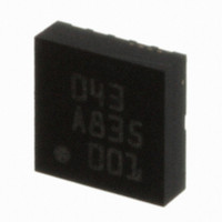
BMA150 Bosch Sensortec, BMA150 Datasheet - Page 24

BMA150
Manufacturer Part Number
BMA150
Description
3-AXIS ACCELEROMETER DIGITAL I/F
Manufacturer
Bosch Sensortec
Specifications of BMA150
Axis
X, Y, Z
Acceleration Range
± 2g, 4g, 8g
Sensitivity
256LSB/g, 128LSB/g, 64LSB/g
Voltage - Supply
2.4 V ~ 3.6 V
Output Type
Digital
Bandwidth
3kHz
Interface
I²C, SPI
Mounting Type
Surface Mount
Package / Case
12-LGA
For Use With
DM180021 - KIT STARTER MPLAB FOR PIC18F MCU828-1013 - BMA150 TRIBOX DEMO BOARD W/USB828-1009 - BMA150 DAUGHTERCARD FOR DEV KIT
Lead Free Status / RoHS Status
Lead free / RoHS Compliant
Other names
0273 141 043
828-1003-2
828-1003-2
Available stocks
Company
Part Number
Manufacturer
Quantity
Price
Company:
Part Number:
BMA150
Manufacturer:
BOSCH
Quantity:
5 888
Part Number:
BMA150
Manufacturer:
BOSCH/博世
Quantity:
20 000
Synchronization of read-out sequence has several advantages:
3.5.3 New_data_x, new_data_y, new_data_z
These bits (New_data_x (02h, 0), new_data_y (04h, 0), new_data_z (06h, 0)) are flags which
are turned at 1 when acceleration registers have been updated. Reading acceleration data MSB
or LSB registers turns the flags at 0. The flag value can be read by microprocessor.
3.5.4 Al_version, ml_version, chip_id
al_version (address 01h, bit 7-4) and ml_version (address 01h, bit 3-0) are used to identify the
chip revision. These codes are programmed with metal layer.
chip_id (address 00h, bit 2-0) is used by customer to be able to recognize BMA150. This code is
fixed to 010b.
Rev. 1.6
© Bosch Sensortec GmbH reserves all rights even in the event of industrial property rights. We reserve all rights of disposal such
as copying and passing on to third parties. BOSCH and the symbol are registered trademarks of Robert Bosch GmbH, Germany.
Note: Specifications within this document are subject to change without notice.
−
−
−
it enables a constant phase shift between acceleration conversion and its corresponding
digital value read by microprocessor
it reduces interface communication by avoiding over-sampling.
potential noise due to serial interface activity perturbation would always be generated
during a less critical phase of the conversion cycle. The maximum delay advised to start
read out acceleration data is 20µs after INT high (window 0 - 80µs).
Triaxial, digital acceleration sensor
Data sheet
BMA150
Page 24
Bosch Sensortec
30 October 2008


