XRP7708EVB Exar Corporation, XRP7708EVB Datasheet - Page 20
XRP7708EVB
Manufacturer Part Number
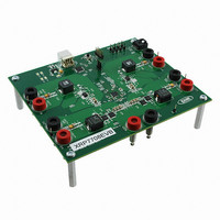
XRP7708EVB
Description
EVAL BOARD FOR XRP7708
Manufacturer
Exar Corporation
Type
PMIC Solutionsr
Specifications of XRP7708EVB
Main Purpose
DC/DC, Step Down
Outputs And Type
*
Voltage - Output
*
Current - Output
*
Voltage - Input
*
Regulator Topology
Buck
Frequency - Switching
*
Board Type
Fully Populated
Utilized Ic / Part
XRP7708
Board Size
6 mm x 6 mm x 0.8 mm
Interface Type
I2C
Maximum Operating Temperature
+ 125 C
Operating Supply Voltage
6.5 V to 20 V
Product
Power Management Development Tools
Sense Voltage (max)
5 mV
Dimensions
6 mm x 6 mm x 0.8 mm
Silicon Manufacturer
Exar
Silicon Core Number
XRP7708
Kit Application Type
Power Management - Voltage Regulator
Application Sub Type
Step Down DC/DC Controller
For Use With/related Products
XRP7708
Lead Free Status / RoHS Status
Lead free / RoHS Compliant
Power - Output
-
Lead Free Status / RoHS Status
Lead free / RoHS Compliant
Other names
1016-1346


The PWM Switching frequency plays an important role on overall power conversion efficiency. As
the switching frequency increase, the switching losses also increase. Please see the APPLICATION
INFORMATION, Typical Performance Data for further examples.
Typically the components become smaller as the frequency increases, as long as the ripple
requirements remain constant. At higher frequency the inductor can be smaller in value and have a
smaller footprint while still maintaining the same current rating.
F
The user of the XRP7708 can choose to use an external source as the primary clock for the
XRP7708. This function can be configured using the SET_SYNC_MODE_CONFIG register. This
register sets the operation of the XRP7708 when an external clock is required. By selecting the
appropriate bit combination the user can configure the IC to function as a master or a slave when
two or more XRP7708s are used to convert power in a system. Automatic clock selection is also
provided to allow operation even if the external clock fails by switching the IC back to an internal
clock.
Even when configured to use an external clock, the chip initially powers up with its internal clock.
The user can set the percent target that the frequency detector will use when comparing the
internal clock with the clock frequency input on the GPIO pin. If the external clock frequency is
detected to be within the window specified by the user, then a switchover will occur to the external
clock. If the IC does not find a clock in the specified frequency target range then the external clock
will not be used and the IC will run on the internal clock that was specified by the user. If the
external clock fails the user can chose to have the internal clock take over, using the automatic
switch back mode in the SET_SYNC_MODE_CONFIG register.
Two XRP7708s can be synchronized together. This Master-Slave configuration is described below.
When the XRP7708 powers up as a master unit after the internal configuration memory is loaded
the unit will send CLK_OUT and SYNC_OUT signals to the slave on the preconfigured GPIO pins.
© 2010 Exar Corporation
Component Selection and Frequency
REQUENCY
External Clock Synchronization
Synchronized Operation as a Master and Slave Unit
•
•
Master
Slave
S
YNCHRONIZATION
Fig. 22:XRP7708 Configured For External Clock Use
F
Q
Q
UNCTION AND
u
u
CLK_IN
a
a
d
d
C
C
h
h
a
a
GPIO1
external clock use
20/27
n
n
Configured for
n
n
XRP7708
E
e
e
XTERNAL
l
l
D
D
i
i
g
g
i
i
t
t
a
a
C
l
l
LOCK
P
P
W
W
M
M
S
S
t
t
e
e
p
p
D
D
o
o
w
w
n
n
X
X
C
C
R
R
o
o
n
P
n
P
Rev. 1.0.3
t
t
7
7
r
r
o
7
o
7
l
l
0
0
l
l
e
e
8
8
r
r
Related parts for XRP7708EVB
Image
Part Number
Description
Manufacturer
Datasheet
Request
R

Part Number:
Description:
Quad Channel Digital Pwm Step Down Controller
Manufacturer:
Exar Corporation
Datasheet:
Part Number:
Description:
BiCMOS Fixed, Quad, Voltage Output, Single or Dual Supply 8-Bit Digital-to-Analog Converter
Manufacturer:
Exar Corporation
Datasheet:
Part Number:
Description:
Manufacturer:
Exar Corporation
Datasheet:
Part Number:
Description:
Voltage-Controlled Oscillator
Manufacturer:
Exar Corporation
Datasheet:
Part Number:
Description:
INTEGRATED LINE TRANSMITTER
Manufacturer:
Exar Corporation
Datasheet:
Part Number:
Description:
Monolithic Function Generator
Manufacturer:
Exar Corporation
Datasheet:
Part Number:
Description:
CMOS Microprocessor Compatible Double-Buffered 12-Bit Digital-to-Analog Converter
Manufacturer:
Exar Corporation
Datasheet:
Part Number:
Description:
CMOS 6 BIT HIGH SPEED ANALOG TO DIGITAL CONVERTER
Manufacturer:
Exar Corporation
Datasheet:
Part Number:
Description:
Manufacturer:
Exar Corporation
Datasheet:
Part Number:
Description:
Manufacturer:
Exar Corporation
Datasheet:
Part Number:
Description:
8-Channel, Voltage Output 10 MHz Input Bandwidth 8-Bit Multiplying DACs with Serial Digital Data Por
Manufacturer:
Exar Corporation
Datasheet:
Part Number:
Description:
15 V CMOS Multiplying10-Bit Digital-to-Analog Converter
Manufacturer:
Exar Corporation
Datasheet:
Part Number:
Description:
Monolithic Function Generator
Manufacturer:
Exar Corporation
Datasheet: