XRP7708EVB Exar Corporation, XRP7708EVB Datasheet - Page 18
XRP7708EVB
Manufacturer Part Number
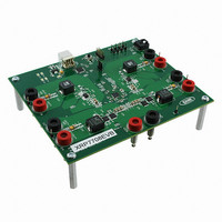
XRP7708EVB
Description
EVAL BOARD FOR XRP7708
Manufacturer
Exar Corporation
Type
PMIC Solutionsr
Specifications of XRP7708EVB
Main Purpose
DC/DC, Step Down
Outputs And Type
*
Voltage - Output
*
Current - Output
*
Voltage - Input
*
Regulator Topology
Buck
Frequency - Switching
*
Board Type
Fully Populated
Utilized Ic / Part
XRP7708
Board Size
6 mm x 6 mm x 0.8 mm
Interface Type
I2C
Maximum Operating Temperature
+ 125 C
Operating Supply Voltage
6.5 V to 20 V
Product
Power Management Development Tools
Sense Voltage (max)
5 mV
Dimensions
6 mm x 6 mm x 0.8 mm
Silicon Manufacturer
Exar
Silicon Core Number
XRP7708
Kit Application Type
Power Management - Voltage Regulator
Application Sub Type
Step Down DC/DC Controller
For Use With/related Products
XRP7708
Lead Free Status / RoHS Status
Lead free / RoHS Compliant
Power - Output
-
Lead Free Status / RoHS Status
Lead free / RoHS Compliant
Other names
1016-1346


P
The XRP7708 allows the user to set the upper and lower bound for a power good signal per
channel.
SET_PWRG_TARG_MIN_CHx register sets the lower bound. Each register has a 20mV LSB
resolution. When the output voltage is within bounds the power good signal is asserted high.
Typically the upper bound should be lower than the over-voltage threshold. In addition, the power
good signal can be delayed by a programmable amount set in the SET_PWRGD_DLY_CHx register.
The power good delay is only set after the soft-start period is finished. If the channel has a pre-
charged condition that falls into the power good region, a power good flag is not set until the soft-
start is finished.
PWM S
The PWM switching frequency is set by choosing the corresponding oscillator frequency and clock
divider ratio in the SET_SW_FREQUENCY register. Bits [6:4] set the oscillator frequency and bits
[2:0] set the clock divider. The tables below summarize the available Main Oscillator and PWM
switching frequency settings in the XRP7708.
There are a number of options that could result in similar PWM switching frequency as shown
above. In general, the chip consumes less power at lower oscillator frequency. When
synchronization to external clock is needed, the user can choose the oscillator frequency to be
© 2010 Exar Corporation
Main Oscillator Frequency
PWM Switching Frequency
OWER
SET_SW_FREQUENCY[6:4]
SET_SW_FREQUENCY[2:0]
Main Oscillator Frequency
G
WITCHING
OOD
The
000
001
010
011
100
101
110
111
Ts
F
LAG
SET_PWRG_TARG_MAX_CHx
F
REQUENCY
Ena ble
Signal
Vout
600KHZ
429KHZ
750KHz
500KHz
375KHz
1.5MHz
1.0MHz
20.8ns
48MHz
000
000
NA
Q
Q
Fig. 20: Channel Soft-Stop Sequence
u
u
a
a
d
d
44.8MHz 41.6MHz 38.4MHz 35.2MHz
467KHZ
400KHZ
933KHz
700KHz
560KHz
350KHz
1.4MHz
Bit [15 :10]
22.3ns
DELAY
001
001
C
C
NA
h
h
a
a
18/27
n
n
n
n
867KHz
650KHz
520KHz
433KHz
370KHz
325KHz
1.3MHz
24ns
PD_DELAY_CHx
e
e
010
010
register
NA
REGISTER
l
l
SET_SW_FREQUENCY[6:4]
D
D
i
i
g
g
800KHz
600KHz
480KHz
400KHz
343KHz
300KHz
1.2MHz
i
i
t
26ns
t
011
011
NA
a
a
FALL TIME
Bit [9:0]
l
l
sets
P
P
W
W
733KHz
550KHz
440KHz
367KHz
314KHz
1.1MHz
28.4ns
M
100
100
M
NA
NA
the
S
S
t
t
e
e
31.25ns
667KHz
500KHz
400KHz
333KHz
1.0MHz
p
p
32MHz
101
101
upper
NA
NA
NA
D
D
o
o
w
w
28.8Mhz
900KHz
600KHz
450KHz
360KHz
300KHz
n
n
34.7ns
110
110
X
X
NA
NA
NA
bound,
C
C
R
R
o
o
n
P
n
P
Rev. 1.0.3
t
t
7
7
25.6MHz
800KHz
533KHz
400KHz
320KHz
r
r
39ns
o
7
o
111
111
7
NA
NA
NA
NA
l
l
0
0
l
l
the
e
e
8
8
r
r
Related parts for XRP7708EVB
Image
Part Number
Description
Manufacturer
Datasheet
Request
R

Part Number:
Description:
Quad Channel Digital Pwm Step Down Controller
Manufacturer:
Exar Corporation
Datasheet:
Part Number:
Description:
BiCMOS Fixed, Quad, Voltage Output, Single or Dual Supply 8-Bit Digital-to-Analog Converter
Manufacturer:
Exar Corporation
Datasheet:
Part Number:
Description:
Manufacturer:
Exar Corporation
Datasheet:
Part Number:
Description:
Voltage-Controlled Oscillator
Manufacturer:
Exar Corporation
Datasheet:
Part Number:
Description:
INTEGRATED LINE TRANSMITTER
Manufacturer:
Exar Corporation
Datasheet:
Part Number:
Description:
Monolithic Function Generator
Manufacturer:
Exar Corporation
Datasheet:
Part Number:
Description:
CMOS Microprocessor Compatible Double-Buffered 12-Bit Digital-to-Analog Converter
Manufacturer:
Exar Corporation
Datasheet:
Part Number:
Description:
CMOS 6 BIT HIGH SPEED ANALOG TO DIGITAL CONVERTER
Manufacturer:
Exar Corporation
Datasheet:
Part Number:
Description:
Manufacturer:
Exar Corporation
Datasheet:
Part Number:
Description:
Manufacturer:
Exar Corporation
Datasheet:
Part Number:
Description:
8-Channel, Voltage Output 10 MHz Input Bandwidth 8-Bit Multiplying DACs with Serial Digital Data Por
Manufacturer:
Exar Corporation
Datasheet:
Part Number:
Description:
15 V CMOS Multiplying10-Bit Digital-to-Analog Converter
Manufacturer:
Exar Corporation
Datasheet:
Part Number:
Description:
Monolithic Function Generator
Manufacturer:
Exar Corporation
Datasheet: