CP2110EK Silicon Laboratories Inc, CP2110EK Datasheet - Page 19
CP2110EK
Manufacturer Part Number
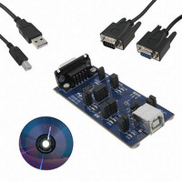
CP2110EK
Description
KIT EVAL FOR CP2110
Manufacturer
Silicon Laboratories Inc
Specifications of CP2110EK
Main Purpose
Interface, USB 2.0 to UART (RS485) Bridge
Embedded
No
Utilized Ic / Part
CP2110
Primary Attributes
Full Speed (12Mbps)
Secondary Attributes
LED Status Indicators
Interface Type
RS-232, USB
Operating Supply Voltage
3.3 V
Product
Interface Development Tools
For Use With/related Products
CP2110
Lead Free Status / RoHS Status
Lead free / RoHS Compliant
Lead Free Status / RoHS Status
Lead free / RoHS Compliant
Other names
336-2003
Available stocks
Company
Part Number
Manufacturer
Quantity
Price
Company:

Part Number:
CP2110EK
Manufacturer:
SiliconL
Quantity:
16


9. Voltage Regulator
The CP2110 includes an on-chip 5 to 3.45 V voltage regulator. This allows the CP2110 to be configured as either a
USB bus-powered device or a USB self-powered device. A typical connection diagram of the device in a bus-
powered application using the regulator is shown in Figure 8. When enabled, the voltage regulator output appears
on the V
characteristics. If the regulator is used to provide V
from Figure 8, but connect REGIN to an on-board 5 V supply, and disconnect it from the VBUS pin.
Connector
Note 1 : VIO can be connected directly to VDD or to a supply as low as 1.8 V to set the I/O interface
Note 2 : Avalanche transient voltage suppression diodes compatible with Full-speed USB should be
Note 3 : An external pull-up is not required, but can be added for noise immunity.
Note 4 : If programming the configuration ROM via USB, add a 4.7 F capacitor between VPP
USB
VBUS
GND
D+
DD
D-
3.45 V Power
pin and can be used to power external devices. See Table 5 for the voltage regulator electrical
voltage.
added at the connector for ESD protection. Use Littelfuse p/n SP0503BAHT or equivalent.
circuitry, and ensure that VDD is at least 3.3 V.
and ground. During a programming operation, do not connect the VPP pin to other
1-5 F
Note 2
Figure 8. Typical Bus-Powered Connection Diagram
Note 1
0.1 F
1 F
VIO
VDD
REGIN
GND
VBUS
D+
D-
DD
Rev. 1.0
in a self-powered application, use the same connections
CP2110
GPIO.3_RS485
GPIO.1_RTS
GPIO.2_CTS
GPIO.5_RXT
GPIO.0_CLK
GPIO.4_TXT
SUSPEND
SUSPEND
GPIO.6
GPIO.7
GPIO.8
GPIO.9
RST
VPP
RX
TX
VIO
and GPIO
Suspend
Standard
Signals
Signals
4.7 F
UART
Note 3
Note 4
4.7 k
CP2110
19
Related parts for CP2110EK
Image
Part Number
Description
Manufacturer
Datasheet
Request
R

Part Number:
Description:
QFN 24/I°/HID USB TO UART BRIDGE
Manufacturer:
Silicon Laboratories Inc

Part Number:
Description:
IC HID USB-TO-UART BRIDGE 24QFN
Manufacturer:
Silicon Laboratories Inc
Datasheet:

Part Number:
Description:
Peripheral Drivers & Components (PCIs) HID USB-UART bridge
Manufacturer:
Silicon Laboratories Inc
Datasheet:
Part Number:
Description:
SMD/C°/SINGLE-ENDED OUTPUT SILICON OSCILLATOR
Manufacturer:
Silicon Laboratories Inc
Part Number:
Description:
Manufacturer:
Silicon Laboratories Inc
Datasheet:
Part Number:
Description:
N/A N/A/SI4010 AES KEYFOB DEMO WITH LCD RX
Manufacturer:
Silicon Laboratories Inc
Datasheet:
Part Number:
Description:
N/A N/A/SI4010 SIMPLIFIED KEY FOB DEMO WITH LED RX
Manufacturer:
Silicon Laboratories Inc
Datasheet:
Part Number:
Description:
N/A/-40 TO 85 OC/EZLINK MODULE; F930/4432 HIGH BAND (REV E/B1)
Manufacturer:
Silicon Laboratories Inc
Part Number:
Description:
EZLink Module; F930/4432 Low Band (rev e/B1)
Manufacturer:
Silicon Laboratories Inc
Part Number:
Description:
I°/4460 10 DBM RADIO TEST CARD 434 MHZ
Manufacturer:
Silicon Laboratories Inc
Part Number:
Description:
I°/4461 14 DBM RADIO TEST CARD 868 MHZ
Manufacturer:
Silicon Laboratories Inc
Part Number:
Description:
I°/4463 20 DBM RFSWITCH RADIO TEST CARD 460 MHZ
Manufacturer:
Silicon Laboratories Inc
Part Number:
Description:
I°/4463 20 DBM RADIO TEST CARD 868 MHZ
Manufacturer:
Silicon Laboratories Inc
Part Number:
Description:
I°/4463 27 DBM RADIO TEST CARD 868 MHZ
Manufacturer:
Silicon Laboratories Inc