CP2110EK Silicon Laboratories Inc, CP2110EK Datasheet - Page 18
CP2110EK
Manufacturer Part Number
CP2110EK
Description
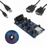
KIT EVAL FOR CP2110
Manufacturer
Silicon Laboratories Inc
Specifications of CP2110EK
Main Purpose
Interface, USB 2.0 to UART (RS485) Bridge
Embedded
No
Utilized Ic / Part
CP2110
Primary Attributes
Full Speed (12Mbps)
Secondary Attributes
LED Status Indicators
Interface Type
RS-232, USB
Operating Supply Voltage
3.3 V
Product
Interface Development Tools
For Use With/related Products
CP2110
Lead Free Status / RoHS Status
Lead free / RoHS Compliant
Lead Free Status / RoHS Status
Lead free / RoHS Compliant
Other names
336-2003
Available stocks
Company
Part Number
Manufacturer
Quantity
Price
Company:

Part Number:
CP2110EK
Manufacturer:
SiliconL
Quantity:
16


CP2110
8. One-Time Programmable ROM
The CP2110 includes an internal, one-time programmable ROM that may be used to customize the USB Vendor ID
(VID), Product ID (PID), Manufacturer String, Product Description String, Power Descriptor, Device Release
Number, Device Serial Number, GPIO configuration, Suspend Pins and Modes as desired for OEM applications. If
the programmable ROM has not been customized, the default configuration data shown in Table 13 and Table 14 is
used.
While customization of the USB configuration data is optional, customizing the VID/PID combination is strongly
recommended. A unique VID/PID will prevent the device from being recognized by any other manufacturer’s
software application. A vendor ID can be obtained from www.usb.org or Silicon Labs can provide a free PID for the
OEM product that can be used with the Silicon Labs VID. All CP2110 devices are pre-programmed with a unique
serial number. It is important to have a unique serial if it is possible for multiple CP2110-based devices to be
connected to the same PC.
Application Note “AN433: CP2110 HID Interface Specification” includes more information about the programmable
values and their valid options. Note that certain items in the PROM are programmed as a group and programming
one of the items in the group prevents further programming of any of the other items in the group.
The configuration data ROM is programmable by Silicon Labs prior to shipment with the desired configuration
information. It can also be programmed in-system over the USB interface by adding a capacitor to the PCB. If the
configuration ROM is to be programmed in-system, a 4.7 µF capacitor must be added between the VPP pin and
ground. No other circuitry should be connected to VPP during a programming operation, and V
3.3 V or higher to successfully write to the configuration ROM.
18
GPIO.0
GPIO.1
GPIO.2
GPIO.3
GPIO.4
GPIO.5
GPIO.6
GPIO.7
GPIO.8
Vendor ID
Product ID
Power Descriptor (Attributes)
Power Descriptor (Max. Power)
Release Number
Manufacturer String
Product Description String
Serial String
Name
Name
Table 14. Default GPIO, UART, and Suspend Configuration Data
GPIO input
RTS
CTS
RS-485 Transceiver Control
TX Toggle
RX Toggle
GPIO input
GPIO input
GPIO push-pull output
Value
Table 13. Default USB Configuration Data
10C4h
EA80h
80h (Bus-powered)
32h (100 mA)
0100h (Release Version 01.00)
“Silicon Laboratories” (62 ASCII characters maximum)
“CP2110 HID USB-to-UART Bridge” (62 ASCII characters maximum)
Unique 8 character ASCII string (30 ASCII characters maximum)
Rev. 1.0
GPIO.9
Flush_Buffers
TX Mode
SUSPEND Mode
SUSPEND Mode
Suspend Latch
RS-485 Level
Clock Divider
Suspend Mode
Name
Value
GPIO push-pull output
Flush TX and RX FIFO on open
Push-pull
Push-pull
Push-pull
0x0000
0x0000
Active High
Divide by 1 (24 MHz)
Value
DD
must remain at
Related parts for CP2110EK
Image
Part Number
Description
Manufacturer
Datasheet
Request
R

Part Number:
Description:
QFN 24/I°/HID USB TO UART BRIDGE
Manufacturer:
Silicon Laboratories Inc

Part Number:
Description:
IC HID USB-TO-UART BRIDGE 24QFN
Manufacturer:
Silicon Laboratories Inc
Datasheet:

Part Number:
Description:
Peripheral Drivers & Components (PCIs) HID USB-UART bridge
Manufacturer:
Silicon Laboratories Inc
Datasheet:
Part Number:
Description:
SMD/C°/SINGLE-ENDED OUTPUT SILICON OSCILLATOR
Manufacturer:
Silicon Laboratories Inc
Part Number:
Description:
Manufacturer:
Silicon Laboratories Inc
Datasheet:
Part Number:
Description:
N/A N/A/SI4010 AES KEYFOB DEMO WITH LCD RX
Manufacturer:
Silicon Laboratories Inc
Datasheet:
Part Number:
Description:
N/A N/A/SI4010 SIMPLIFIED KEY FOB DEMO WITH LED RX
Manufacturer:
Silicon Laboratories Inc
Datasheet:
Part Number:
Description:
N/A/-40 TO 85 OC/EZLINK MODULE; F930/4432 HIGH BAND (REV E/B1)
Manufacturer:
Silicon Laboratories Inc
Part Number:
Description:
EZLink Module; F930/4432 Low Band (rev e/B1)
Manufacturer:
Silicon Laboratories Inc
Part Number:
Description:
I°/4460 10 DBM RADIO TEST CARD 434 MHZ
Manufacturer:
Silicon Laboratories Inc
Part Number:
Description:
I°/4461 14 DBM RADIO TEST CARD 868 MHZ
Manufacturer:
Silicon Laboratories Inc
Part Number:
Description:
I°/4463 20 DBM RFSWITCH RADIO TEST CARD 460 MHZ
Manufacturer:
Silicon Laboratories Inc
Part Number:
Description:
I°/4463 20 DBM RADIO TEST CARD 868 MHZ
Manufacturer:
Silicon Laboratories Inc
Part Number:
Description:
I°/4463 27 DBM RADIO TEST CARD 868 MHZ
Manufacturer:
Silicon Laboratories Inc