TWR-ADCDAC-LTC Freescale Semiconductor, TWR-ADCDAC-LTC Datasheet - Page 33
TWR-ADCDAC-LTC
Manufacturer Part Number
TWR-ADCDAC-LTC
Description
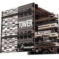
MOD ADC DAC TOWER LINEAR TECH
Manufacturer
Freescale Semiconductor
Type
A/Dr
Specifications of TWR-ADCDAC-LTC
Main Purpose
Data Conversion, ADC, DAC
Embedded
No
Utilized Ic / Part
LTC1859, LTC2498, LTC2600, LTC2704, LTC3471
Primary Attributes
2 Analog to Digital Converters, 2 Digital to Analog Converters
Secondary Attributes
For use with Freescale Tower System
Maximum Clock Frequency
50 MHz
Interface Type
Touch Sense, ULPI, UART, IrDA, I2S,
Product
Data Conversion Development Tools
Silicon Manufacturer
Freescale
Silicon Core Number
LTC2704, LTC2600, LTC1859, LTC2498, LTC3471 & LTC6655-5
Kit Application Type
Data Converter
Application Sub Type
ADC, DAC
Rohs Compliant
Yes
Lead Free Status / RoHS Status
Lead free / RoHS Compliant
For Use With/related Products
Kinetis MCU
Lead Free Status / Rohs Status
Compliant


Freescale, the Freescale logo, AltiVec, C-5, CodeTEST, CodeWarrior, ColdFire, C-Ware, mobileGT, PowerQUICC, StarCore, and Symphony are trademarks of Freescale Semiconductor, Inc.,
Reg. U.S. Pat. & Tm. Off. BeeKit, BeeStack, CoreNet, the Energy Efficient Solutions logo, Flexis, MXC, Platform in a Package, Processor Expert, QorIQ, QUICC Engine, SMARTMOS, TurboLink
and VortiQa are trademarks of Freescale Semiconductor, Inc. All other product or service names are the property of their respective owners. © 2010 Freescale Semiconductor, Inc.
K10 K20 & K30 K40 = Add USB with almost zero changes
K10 K30 & K20 K40 = Add Segment LCD with minimal board layout changes
K20 K60 = Add Ethernet with NO changes
DIGITAL I/O = UART, SPI, I2C, CAN, TIMER, etc.
The only difference will be 4 extra USB pins and 4 less digital I/O pins
Digital & Analog I/O signals maintain placement order
Segment LCD signals are muxed with existing Digital & Analog I/O signals
Most Digital I/O signals muxed with Segment LCD signals become available on added pins by larger package
All Ethernet signals are muxed with existing Digital & Analog I/O signals
General Purpose
DIGITAL I/O
DIGITAL I/O
48-pin
K10
48-pin
K20
USB
USB
ANALOG I/O = OSC, ADC, CMP, etc.
Pin Compatibility Across Families
96 segments
64-pin or 80-pin
(8 x 12)
96 segments
DIG / ANA I/O + LCD
(8 x 12)
64-pin or 80-pin
DIG / ANA I/O + sLCD
DIGITAL I/O
DIGITAL I/O
K30
34
34
USB + sLCD
192 segments
K40
(8 x 24)
192 segments
(8 x 24)
USB
LCD
power
pins
TM
Related parts for TWR-ADCDAC-LTC
Image
Part Number
Description
Manufacturer
Datasheet
Request
R

Part Number:
Description:
Manufacturer:
Freescale Semiconductor, Inc
Datasheet:
Part Number:
Description:
Manufacturer:
Freescale Semiconductor, Inc
Datasheet:
Part Number:
Description:
Manufacturer:
Freescale Semiconductor, Inc
Datasheet:
Part Number:
Description:
Manufacturer:
Freescale Semiconductor, Inc
Datasheet:
Part Number:
Description:
Manufacturer:
Freescale Semiconductor, Inc
Datasheet:
Part Number:
Description:
Manufacturer:
Freescale Semiconductor, Inc
Datasheet:
Part Number:
Description:
Manufacturer:
Freescale Semiconductor, Inc
Datasheet:
Part Number:
Description:
Manufacturer:
Freescale Semiconductor, Inc
Datasheet:
Part Number:
Description:
Manufacturer:
Freescale Semiconductor, Inc
Datasheet:
Part Number:
Description:
Manufacturer:
Freescale Semiconductor, Inc
Datasheet:
Part Number:
Description:
Manufacturer:
Freescale Semiconductor, Inc
Datasheet:
Part Number:
Description:
Manufacturer:
Freescale Semiconductor, Inc
Datasheet:
Part Number:
Description:
Manufacturer:
Freescale Semiconductor, Inc
Datasheet:
Part Number:
Description:
Manufacturer:
Freescale Semiconductor, Inc
Datasheet:
Part Number:
Description:
Manufacturer:
Freescale Semiconductor, Inc
Datasheet: