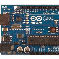
A000046 Arduino, A000046 Datasheet - Page 86
A000046
Manufacturer Part Number
A000046
Description
MCU, MPU & DSP Development Tools Uno
Manufacturer
Arduino
Series
-r
Type
MCUr
Specifications of A000046
Processor To Be Evaluated
ATmega328
Interface Type
USB, I2C, SPI
Dimensions
2.7 in x 2.1 in
Operating Supply Voltage
5 V
Contents
Board
Lead Free Status / RoHS Status
Lead free / RoHS Compliant
For Use With/related Products
ATmega328


ATmega48PA/88PA/168PA/328P
The alternate pin configuration is as follows:
• RESET/PCINT14 – Port C, Bit 6
RESET, Reset pin: When the RSTDISBL Fuse is programmed, this pin functions as a normal I/O
pin, and the part will have to rely on Power-on Reset and Brown-out Reset as its reset sources.
When the RSTDISBL Fuse is unprogrammed, the reset circuitry is connected to the pin, and the
pin can not be used as an I/O pin.
If PC6 is used as a reset pin, DDC6, PORTC6 and PINC6 will all read 0.
PCINT14: Pin Change Interrupt source 14. The PC6 pin can serve as an external interrupt
source.
• SCL/ADC5/PCINT13 – Port C, Bit 5
SCL, 2-wire Serial Interface Clock: When the TWEN bit in TWCR is set (one) to enable the 2-
wire Serial Interface, pin PC5 is disconnected from the port and becomes the Serial Clock I/O
pin for the 2-wire Serial Interface. In this mode, there is a spike filter on the pin to suppress
spikes shorter than 50 ns on the input signal, and the pin is driven by an open drain driver with
slew-rate limitation.
PC5 can also be used as ADC input Channel 5. Note that ADC input channel 5 uses digital
power.
PCINT13: Pin Change Interrupt source 13. The PC5 pin can serve as an external interrupt
source.
• SDA/ADC4/PCINT12 – Port C, Bit 4
SDA, 2-wire Serial Interface Data: When the TWEN bit in TWCR is set (one) to enable the 2-wire
Serial Interface, pin PC4 is disconnected from the port and becomes the Serial Data I/O pin for
the 2-wire Serial Interface. In this mode, there is a spike filter on the pin to suppress spikes
shorter than 50 ns on the input signal, and the pin is driven by an open drain driver with slew-
rate limitation.
PC4 can also be used as ADC input Channel 4. Note that ADC input channel 4 uses digital
power.
PCINT12: Pin Change Interrupt source 12. The PC4 pin can serve as an external interrupt
source.
• ADC3/PCINT11 – Port C, Bit 3
PC3 can also be used as ADC input Channel 3. Note that ADC input channel 3 uses analog
power.
PCINT11: Pin Change Interrupt source 11. The PC3 pin can serve as an external interrupt
source.
• ADC2/PCINT10 – Port C, Bit 2
PC2 can also be used as ADC input Channel 2. Note that ADC input channel 2 uses analog
power.
PCINT10: Pin Change Interrupt source 10. The PC2 pin can serve as an external interrupt
source.
86
8161D–AVR–10/09
Related parts for A000046
Image
Part Number
Description
Manufacturer
Datasheet
Request
R

Part Number:
Description:
Daughter Cards & OEM Boards ARDUINO UNO PROTO PCB REV 3
Manufacturer:
Arduino
Part Number:
Description:
Daughter Cards & OEM Boards ARDUINO SHIELD PROTO KIT REV 3
Manufacturer:
Arduino
Part Number:
Description:
Daughter Cards & OEM Boards ARDUINO MEGA PROTO KIT REV 3
Manufacturer:
Arduino
Part Number:
Description:
Daughter Cards & OEM Boards ARDUINO MEGA PROTO PCB REV 3
Manufacturer:
Arduino
Part Number:
Description:
Development Boards & Kits - AVR ARDUINO STARTER KIT W/ UNO REV3
Manufacturer:
Arduino
Part Number:
Description:
RF Development Tools ARDUINO SHIELD WIRELESS PROTO
Manufacturer:
Arduino
Datasheet:
Part Number:
Description:
RF Development Tools ARDUINO SHIELD WIRELESS WITH SD
Manufacturer:
Arduino
Datasheet:

Part Number:
Description:
Development Software Getting started w/Arduino
Manufacturer:
Arduino

Part Number:
Description:
Ethernet Modules & Development Tools Ethernet Shield for Arduino
Manufacturer:
Arduino

Part Number:
Description:
MCU, MPU & DSP Development Tools LilyPad Arduino Main Board
Manufacturer:
Arduino

Part Number:
Description:
ARDUINO NANO Board
Manufacturer:
Arduino
Datasheet:
Part Number:
Description:
Ethernet Modules & Development Tools ETHERNET SHEILD PoE FOR ARDUINO
Manufacturer:
Arduino
Datasheet:

Part Number:
Description:
ATMEGA328 MCU IC W/ Arduino UNO Bootloader
Manufacturer:
Arduino
Datasheet:
Part Number:
Description:
Memory Cards MICRO SD CARD 1GB WITH SD ADAPTER
Manufacturer:
Arduino