AVR-P28N-8MHz Olimex Ltd., AVR-P28N-8MHz Datasheet
AVR-P28N-8MHz
Specifications of AVR-P28N-8MHz
Available stocks


Related parts for AVR-P28N-8MHz


AVR-P28N-8MHz Summary of contents
Page 1
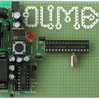
... AVR-P28 development board All boards produced by Olimex are ROHS compliant Copyright(c) 2009, OLIMEX Ltd, All rights reserved Users Manual Revision A, November 2005 Page 1 ...
Page 2
... BOARD USE REQUIREMENTS: Cables: The cable you will need depends on the programmer/debugger you use. If you use AVR-PG1, you will need RS232 cable, if you use AVR-PG2, you will need LPT cable, if you use AVR-ISP500, need 1.8 meter USB A-B cable. ...
Page 3
... Hardware: Programmer – one of the Olimex AVR Programmers: AVR-PG1, AVR- PG2, AVR-ISP500, AVR-ISP500-TINY, AVR-ISP500-ISO. SCHEMATIC: Page 3 ...
Page 4
... AVR-P28 isypically power supplied with min 9.0V DC max 12.0V DC, or min 6.0V AC max 9.0V AC. RESET CIRCUIT: AVR-P28 reset circuit includes pin 5 of ICSP connector, pin 1 of U1, Reset scheme – U3 and RESET button (RST). CLOCK CIRCUIT: Quartz crystal 8MHz is connected to AVR Microcontroller pin 9 (XTAL1) and pin 10 (XTAL2) ...
Page 5
JUMPER DESCRIPTION: J1 When 1-2 are shorted – RTS is connected to terminal pin RTS/DTR. When 2-3 are shorted – DTR is connected to terminal pin RTS/DTR. Default state is 1-2. LED_J When this jumper is open – LED is ...
Page 6
... Not connected Note1: RTS and DTR is connected to terminal pins via jumper J1, which position was described above. Note2: RX RS232 driver pins have to be connected to AVR microcontroller pin - TXD/PD1 (PIN 3). TX RS232 driver pins have to be connected to AVR microcontroller pin - RXD/PD0 (PIN 2). ...
Page 7
MECHANICAL DIMENSIONS: Page 7 ...
Page 8
... AVAILABLE DEMO SOFTWARE: AVR-P28 + ATmega8 Blinkng LED AVR-P28 + ATmega8 UART demo AVR-P28 + ATmega8 Button demo ORDER CODE: AVR-P28-8MHz completely assembled and tested with 8Mhz oscillator AVR-P28/PCB ONLY How to order? You can order to us directly or by any of our distributors. Check our web Revision history: REV ...
Page 9
... However all warranties implied or expressed including but not limited to implied warranties of merchantability or fitness for purpose are excluded. This document is intended only to assist the reader in the use of the product. OLIMEX Ltd. shall not be liable for any loss or damage arising from the use of any information in this document or any error or omission in such information or any incorrect use of the product ...