RDK-242 Power Integrations, RDK-242 Datasheet - Page 18
RDK-242
Manufacturer Part Number
RDK-242
Description
Power Management Modules & Development Tools TOPSwitch-JX REF. DESIGN KIT
Manufacturer
Power Integrations
Type
MOSFET & Power Driverr
Datasheet
1.RDK-242.pdf
(59 pages)
Specifications of RDK-242
Input Voltage
85 VAC to 264 VAC
Output Voltage
12 V
Maximum Operating Temperature
+ 40 C
Minimum Operating Temperature
0 C
Operating Supply Voltage
85 VAC to 264 VAC
Product
Power Management Modules


7.5 Transformer Construction
Outer insulation
Final Assembly
(Secondary)
preparation
(Shielding)
Insulation
Insulation
Insulation
Insulation
(Primary)
Winding
(Cancel)
Margin
(Bias)
WD1
WD2
WD3
WD4
WD5
Power Integrations, Inc.
Tel: +1 408 414 9200 Fax: +1 408 414 9201
www.powerint.com
Place the bobbin item [2] on the mandrel such that primary side on the left and
secondary side on the right. Winding direction is clockwise direction.
Apply margin tape item [7] on both sides of bobbin and for all windings.
Start at pin 6, apply Teflon tubes item [8] at start ends, wind 13 bifilar turns of item [4]
from left to right. At the last turn, cut the wires and leave no connect.
Apply 1 layer of tape item [9].
Start at pin 4, apply Teflon tube item [8] at start end, wind 29 turns of item [3] from left
to right, place 1 layer of tape item [10]. Continue winding from right to left with another
29 turns, at the last turn also apply Teflon tube item [8] and end at pin 6.
Apply 1 layer of tape item [9].
Use copper foil tape item [12], see figure 3 above, start with no connect; wind 1 turn
(over lapped- but separate with tape to avoid shortage), and end with pin 6.
Apply 3 layers of tape item [8].
Start at pin 7, 8, apply Teflon tubes item [8] at start ends, wind 6 bifilar turns of item [5]
from right to left, at the last turn bring the wires back to the left, also apply Teflon tubes
at the wire ends, and finish at pin 11,12.
Apply 3 layers of tape item [9].
Start at pin 1, apply Teflon tubes item [8] at start ends, wind 6 bifilar turns of item [6]
from left to right, at the last turn bring the wires back to the left, also apply Teflon tubes
at the wire ends, and finish at pin 1.
Apply 2 layers of tape item [9].
Grind core. Cover outside the core with tape item [11]. Assemble core and varnish [13]
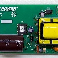
Figure 8 – Completed Transformer.
Page 18 of 59
Related parts for RDK-242
Image
Part Number
Description
Manufacturer
Datasheet
Request
R

Part Number:
Description:
KIT REF DESIGN TOP HX FOR TOP258
Manufacturer:
Power Integrations
Datasheet:

Part Number:
Description:
KIT REF DESIGN LINKSWITCH 2
Manufacturer:
Power Integrations
Datasheet:

Part Number:
Description:
KIT REF DESIGN 1.2W PS TN FAMILY
Manufacturer:
Power Integrations
Datasheet:

Part Number:
Description:
KIT REF DESIGN 36-72W MOTOR DRVR
Manufacturer:
Power Integrations
Datasheet:

Part Number:
Description:
KIT REF DESIGN FOR LNK457D
Manufacturer:
Power Integrations
Datasheet:

Part Number:
Description:
REFERENCE DESIGN LINKSWITCH-PH
Manufacturer:
Power Integrations
Datasheet:

Part Number:
Description:
Specifications: Manufacturer: Power Integrations ; Output Voltage: 380 VDC ; Input / Supply Voltage (Max): 264 VAC ; Input / Supply Voltage (Min): 90 VAC ; Mounting Style: Through Hole ; Output Current: 0.913 A ; Output Power: 347 W
Manufacturer:
Power Integrations, Inc.
Part Number:
Description:
Power Management IC Development Tools REF DESIGN RDR-292 PFF LED STREET LIGHT
Manufacturer:
Power Integrations

Part Number:
Description:
KIT REF DESIGN FOR LNK403EG
Manufacturer:
Power Integrations
Datasheet:

Part Number:
Description:
KIT REF DESIGN FOR LNK406EG
Manufacturer:
Power Integrations
Datasheet:

Part Number:
Description:
KIT REF DESIGN DG CAPZERO
Manufacturer:
Power Integrations
Datasheet:

Part Number:
Description:
KIT REF DESIGN LINKSWITCH-CV
Manufacturer:
Power Integrations
Datasheet:

Part Number:
Description:
KIT REF DESIGN PFS762HG
Manufacturer:
Power Integrations
Datasheet:
Part Number:
Description:
Specifications: Family: Eval Boards - DC/DC & AC/DC (Off-Line) SMPS ; Series: HiperLCS™ ; Main Purpose: DC/DC, Step Down ; Outputs and Type: 1, Isolated ; Power - Output: 150W ; Voltage - Output: 24V ; Current - Output: 6.25A ; Voltage - Input:
Manufacturer:
Power Integrations, Inc.
Datasheet:

Part Number:
Description:
KIT REFERENCE DESIGN W/TN376PN
Manufacturer:
Power Integrations
Datasheet: