LQ043T1DG01 Sharp Microelectronics, LQ043T1DG01 Datasheet
LQ043T1DG01
Specifications of LQ043T1DG01
Available stocks


Related parts for LQ043T1DG01


LQ043T1DG01 Summary of contents
Page 1
... P S RODUCT PECIFICATIONS LQ043T1DG01 TFT-LCD Module Spec. Issue Date: July, 21 2006 AVC Liquid Crystal Displays Group No: LCY-W-06602A ...
Page 2
...
Page 3
...
Page 4
This publication is the proprietary of SHARP and is copyrighted, with all rights reserved. Under the copyright laws, no part of this publication may be reproduced or transmitted in any form or by any means, electronic or mechanical for any ...
Page 5
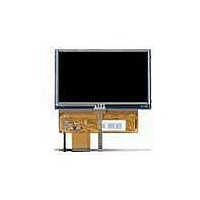
... Applicable Scope This specification is applicable to TFT-LCD Module “LQ043T1DG01”. 2. General Description This module is a color active matrix LCD module incorporating amorphous silicon TFT (Thin Film Transistor composed of a color TFT-LCD panel, driver ICs, Input FPC, a back light unit and a touch panel. Graphics and texts can be displayed on a 480× ...
Page 6
Input Terminal Names and Functions 4-1. TFT LCD Panel Driving (Reference Connector: Hirose Electric CO., LTD. Product No.: FH12A-40S-0.5SH (55) Top contact type) ※ The Bottom contact type can be selected according to side of mounted connector and terminal ...
Page 7
Backlight 0.5mmP 4Pin FPC (Reference Connector: Kyocera Elco Corporation Product No.: 6298 Bottom contact type) ※ The Bottom contact type can be selected according to side of mounted connector and terminal side of FPC. Terminal Signal No ...
Page 8
Electrical Characteristics 6-1. TFT LCD Panel Driving Item +3.3V DC voltage power supply DC current +5V DC voltage power supply DC current Permissive input ripple voltage Input voltage (Low) Input voltage (High) Input current (Low) Input current (High) ※ ...
Page 9
Sequences of supply voltage and signals 2.3V 0.3V VCC AVDD CK Hsync,Vsync DATA 【Note 2】 DISP LCD display LED B/L ON/OFF Timing (example) ◎ Please do not supply AVDD before VCC. ◎ It discharges and boost up voltage ...
Page 10
DISP DISP VSYNC VSYNC HSYNC HSYNC 【 Allowed Timing 】 DISP DISP VSYNC VSYNC HSYNC HSYNC 【Note 3】Typical current situation: 256-gray-bar pattern 【Note 4】CK, R0~R7, G0~G7,B0~B7,Hsync,Vsync,DISP ...
Page 11
Note 5 】 An example of rush current measurement ◎Measurement conditions ・Power supply voltage VCC : 3.3V AVDD : 5.0V ・Disp signal ・Other input signals ・Measurement system ・rush current measurement timing 2.3V VCC 0.3V Rising Time AVDD 0.01ms Vsync ...
Page 12
Back light driving The back light system has nine LEDs Parameter Symbol V Rated Voltage BL I Rated Current L 7. Timing characteristics of input signals An input signal timing waveform is shown in Fig. 2. 7-1 Timing characteristics ...
Page 13
Timing details THp=41CLK Horizontal synchronizing signals (Hsync) THb=2CLK clock signal (CK) C1* C2* (clock count) ...
Page 14
Input Data Signals and Display Position on the screen D1,DH1 D2,DH1 D1,DH2 D2,DH2 D1,DH3 D1,DH272 ...
Page 15
Input Signals, Basic Display Colors and Gray Scale of Each Color Colors & Gray Gray Scale LSB Scale - Black Blue - Green ...
Page 16
Optical Characteristics Module characteristics Parameter Symbol θ21,θ22 Viewing Horizontal angle θ11 Vertical range θ12 Contrast ratio CR Response Rise τ Time Decay τ Chromaticity of White X Luminance of white Uniformity ※ The optical characteristics measurements are operated under ...
Page 17
Note 1 】Definitions of viewing angle range 6 o’clock 【 Note 2 】Definition of contrast ratio The contrast ratio is defined as the following C ontrast ratio 【 Note 3 】Definition of response time The response time is defined ...
Page 18
Note 5 】Definition of Uniformity. = Uniformity The brightness should be measured on the 9-point as shown in the following figure. Minimum Brightness × 100 (%) Maximum Brightness 1/6 1/6 LCY-W-06602A Page ...
Page 19
Touch panel characteristics Parameter Input voltage Resistor between terminals (XL-XR) Resistor between terminals (YU-YD) Line linearity (X direction) Line linearity (Y direction) Insulation resistance Minimum tension for detecting 11. Mechanical characteristics 11-1) FPC (for LCD panel) characteristics (1) Specific ...
Page 20
Handling of modules 12-1 Inserting the FPC into its connector and pulling it out. ① Be sure to turn off the power supply and the signals when inserting or disconnecting the cable. ② Please insert for too much stress ...
Page 21
Others ① Regarding storage of LCD modules, avoid storing them at direct sunlight-situation. You are requested to store under the following conditions: (Environmental conditions of temperature/humidity for storage) (1) Temperature: 0~40°C (2) Relative humidity : 95% or less ・ ...
Page 22
Reliability test items No. Test item 1 High temperature storage test 2 Low temperature storage test High temperature 3 & high humidity operation test 4 High temperature operation test 5 Low temperature operation test Vibration test 6 (non- operating) ...
Page 23
... The standard regarding the grade of color LCD displaying modules should be based on the delivery inspection standard. 16. Lot No. marking The lot No. will be indicated on individual labels. The location is as shown Indication Label 17. LCD module packing carton Model No LQ043T1DG01 ○○○○○○○○ LCY-W-06602A Page Lot No ...
Page 24
Others 1 Disassembling the module can cause permanent damage and you should be strictly avoided. 2 Please be careful that you don’t keep the screen displayed fixed pattern image for a long time, since retention may occur ...
Page 25
Outline dimension LCY-W-06602A Page Fig.1 ...
Page 26
... ALL EXPRESS AND IMPLIED WARRANTIES, INCLUDING THE WARRANTIES OF MERCHANTABILITY, FITNESS FOR USE AND FITNESS FOR A PARTICULAR PURPOSE, ARE SPECIFICALLY EXCLUDED event will SHARP be liable any way responsible, for any incidental or consequential economic or property damage. NORTH AMERICA SHARP Microelectronics of the Americas 5700 NW Pacific Rim Blvd. Camas, WA 98607, U.S.A. Phone: (1) 360-834-2500 ...