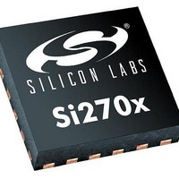
SI2707-A10-GM Silicon Laboratories Inc, SI2707-A10-GM Datasheet - Page 8

SI2707-A10-GM
Manufacturer Part Number
SI2707-A10-GM
Description
AMPLIFIER AUDIO CLASS D 24QFN
Manufacturer
Silicon Laboratories Inc
Type
Class Dr
Datasheet
1.SI2704-A10-GM.pdf
(46 pages)
Specifications of SI2707-A10-GM
Output Type
2-Channel (Stereo) with Stereo Headphones
Package / Case
24-VFQFN Exposed Pad
Max Output Power X Channels @ Load
5W x 2 @ 3 Ohm
Voltage - Supply
4 V ~ 6.6 V
Features
Depop, I²S, Short-Circuit and Thermal Protection, Tone and Volume Control
Mounting Type
Surface Mount
Product
Class-D
Output Power
5 W
Thd Plus Noise
0.1 %
Supply Current
100 mA
Maximum Operating Temperature
+ 85 C
Mounting Style
SMD/SMT
Audio Load Resistance
8 Ohms
Input Offset Voltage
Minimum Operating Temperature
Lead Free Status / RoHS Status
Lead free / RoHS Compliant
Other names
336-1928
Available stocks
Company
Part Number
Manufacturer
Quantity
Price
Table 7. I
(V
Si2704/05/06/07-A10
Table 5. AC Characteristics—Class D Amplifier (Continued)
(V
8
Table 6. AC Characteristics—PWM Digital to Analog Converter
(V
DCLK Input Cycle Time
DCLK Input Pulse Width High
DCLK Input Pulse Width Low
DFS Setup Time to DCLK↑
DFS Hold Time after DCLK↑
DOUT Output Delay
Capacitive Loading
Power Supply Rejection Ratio
Crosstalk
Efficiency
Output Pulse Repetition Frequency
Notes:
Total Harmonic Distortion + Noise
Signal to Noise Ratio/Dynamic Range
Output Voltage Swing
Output Voltage Common Mode Bias
Output Load— Resistance
Output Load— Capacitance
IO
DD
DD
= 1.62 to 3.6 V, T
1. Measured at filter output. Power measured at the chip output is greater.
2. Guaranteed by characterization.
3. Measured relative to the integrated noise floor in Spread mode. Guaranteed by characterization.
4. Does not include filter efficiency losses.
= 2.7 to 3.6 V, V
= 2.7 to 3.6 V, V
4
2
Parameter
S Digital Audio Interface Characteristics
Parameter
A
IO
IO
= –20 to +85 °C, unless otherwise noted).
= 1.62 to 3.6 V, V
= 1.62 to 3.6 V, VOL = 0 dBFS, T
t
T
CYC:DCLK
t
t
t
Symbol
t
LO:DCLK
SU:DCLK
HD:DCLK
HI:DCLK
PD:DCLK
PP
C
= 6.6 V, R
B
PSRR
PRF
η
Symbol
THD+N
Voutcm
R
C
SNR
Vout
load
load
Test Condition
L
= 8 Ω, VOL = 0 dBFS, T
f = 1 kHz, half rate PWM and
A
P
= -20 to +85 °C, unless otherwise noted).
Rev. 0.6
O
200 mV
= –3 dBFS, f = 1 kHz;
f = 1 kHz, Unweighted
AC coupling capacitor
f = 1 kHz, A-weighted
Half Rate PWM
10 ns slew rate
Full Rate PWM
supply ripple
Test Condition
f = 1 kHz
AC coupled
PP
f = 1 kHz
, f
r
= 400 Hz
t
t
CYC:DCLK
CYC:DCLK
0.4 x
0.4 x
Min
A
70
10
—
5
0
= –20 to +85 °C, unless otherwise noted.)
Typ
—
—
—
—
—
—
—
—
—
—
—
—
Min
0.1
—
—
—
—
—
5
–92
480
960
50
88
t
t
0.02
Typ
CYC:DCLK
CYC:DCLK
0.8
88
85
—
—
1
0.6 x
0.6 x
Max
35
15
—
—
—
Max
—
—
—
—
—
50
—
—
—
—
—
1
Unit
kHz
kHz
Unit
V
pF
ns
ns
ns
ns
ns
ns
dB
dB
%
dB
dB
kΩ
µF
%
P-P
V


