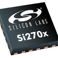
SI2707-A10-GM Silicon Laboratories Inc, SI2707-A10-GM Datasheet - Page 34

SI2707-A10-GM
Manufacturer Part Number
SI2707-A10-GM
Description
AMPLIFIER AUDIO CLASS D 24QFN
Manufacturer
Silicon Laboratories Inc
Type
Class Dr
Datasheet
1.SI2704-A10-GM.pdf
(46 pages)
Specifications of SI2707-A10-GM
Output Type
2-Channel (Stereo) with Stereo Headphones
Package / Case
24-VFQFN Exposed Pad
Max Output Power X Channels @ Load
5W x 2 @ 3 Ohm
Voltage - Supply
4 V ~ 6.6 V
Features
Depop, I²S, Short-Circuit and Thermal Protection, Tone and Volume Control
Mounting Type
Surface Mount
Product
Class-D
Output Power
5 W
Thd Plus Noise
0.1 %
Supply Current
100 mA
Maximum Operating Temperature
+ 85 C
Mounting Style
SMD/SMT
Audio Load Resistance
8 Ohms
Input Offset Voltage
Minimum Operating Temperature
Lead Free Status / RoHS Status
Lead free / RoHS Compliant
Other names
336-1928
Available stocks
Company
Part Number
Manufacturer
Quantity
Price
Si2704/05/06/07-A10
6. Pin Descriptions
6.1. 24-Pin QFN Package
34
Pin Number
GND PAD
10
11
12
13
14
15
16
17
18
19
20
21
22
23
24
1
2
3
4
5
6
7
8
9
OUTSEL/MFP2
AUXOR
OUTPR
OUTNR
AUXOL
OUTNL
OUTPL
GNDR
Name
CLKO
VPPR
GNDL
DCLK
SCLK
MFP3
MFP1
VPPL
XTLO
SDIO
GND
XTLI
VDD
RST
DFS
DIN
VIO
Low voltage ground for VDD. Connect to PCB ground plane.
I
I
I/O supply voltage.
Serial clock input for I
Serial data input/output for I
Buffered reference clock output. Configures 2-Wire address on RST.
Multi-function pin 3.
PWMDAC left channel analog output on Si2705/07 (Reserved on Si2704/06).
PWMDAC right channel analog output on Si2705/07 (Reserved on Si2704/06).
Multi-function pin 1.
Output select three-level control input: 2.0, 2.1 or line out mode.
Right channel power stage supply voltage.
Right channel power stage “P” output.
Right channel power stage “N” output.
Right channel power stage ground.
Left channel power stage ground.
Left channel power stage “N” output.
Left channel power stage “P” output.
Left channel power stage supply voltage.
Device reset (active low) input.
External crystal output.
Reference clock or external crystal input.
Low voltage supply voltage.
I
2
2
2
S digital I/O data clock.
S digital data input port.
S digital I/O data frame synch.
Figure 25. Pin Configuration
DCLK
CLKO
Table 18. Pin Descriptions
SCLK
SDIO
DIN
VIO
1
2
3
4
5
6
24
7
24-Pin QFN Package
23
8
Top Down View
Rev. 0.6
(Back Paddle)
GND PAD
22
9
21
10
2
C-compliant 2-Wire control interface.
20
11
19
12
2
C-compliant 2-Wire control interface.
18
17
16
15
14
13
OUTPL
OUTNL
GNDL
GNDR
OUTNR
OUTPR
Function


