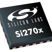
SI2707-A10-GM Silicon Laboratories Inc, SI2707-A10-GM Datasheet - Page 19

SI2707-A10-GM
Manufacturer Part Number
SI2707-A10-GM
Description
AMPLIFIER AUDIO CLASS D 24QFN
Manufacturer
Silicon Laboratories Inc
Type
Class Dr
Datasheet
1.SI2704-A10-GM.pdf
(46 pages)
Specifications of SI2707-A10-GM
Output Type
2-Channel (Stereo) with Stereo Headphones
Package / Case
24-VFQFN Exposed Pad
Max Output Power X Channels @ Load
5W x 2 @ 3 Ohm
Voltage - Supply
4 V ~ 6.6 V
Features
Depop, I²S, Short-Circuit and Thermal Protection, Tone and Volume Control
Mounting Type
Surface Mount
Product
Class-D
Output Power
5 W
Thd Plus Noise
0.1 %
Supply Current
100 mA
Maximum Operating Temperature
+ 85 C
Mounting Style
SMD/SMT
Audio Load Resistance
8 Ohms
Input Offset Voltage
Minimum Operating Temperature
Lead Free Status / RoHS Status
Lead free / RoHS Compliant
Other names
336-1928
Available stocks
Company
Part Number
Manufacturer
Quantity
Price
Si2704/05/06/07-A10
nominally 20 kHz wide and tunable in 5 kHz increments from 520 to 1710 kHz, virtually equalizing the noise level
across the band. The noise-free notch can be dynamically tuned during normal operation without adversely
affecting the internal audio processing or the differential output signal integrity.
Spread Mode PWM with the tunable noise-free notch is useful for systems in which the Si2705/07 needs to co-exist
with an AM radio receiver. In normal AM radio operation, the system MCU programs the noise-free notch
frequency in the Si2705/07 to the same frequency as the AM radio to inhibit PWM switching noise from interfering
with radio reception. Because Spread Mode PWM is also engaged, switching noise outside of the noise-free notch
band is also suppressed for mitigating broadband EMI radiation
The noise-free notch can be placed at different frequencies by programming property PWM_AM_TUNE_FREQ.
More information on the complete range of programming parameters and settings available for optimized operation
can be found in the “AN469: Si270x Programming Guide”.
Figure 13. PWM CM Spectrum for Spread Mode PWM with Noise-Free Notch
4.2. Operating Modes
The Si2704/05/06/07 features four operating modes: one active mode (Active) and three low power modes
(Standby, Sleep and Power Down). The low power modes differ on power consumption and wake up times,
providing the flexibility to meet system design requirements. See Table 3, “DC Characteristics—Supplies and
Interfaces,” on page 6 for additional information on startup times and power consumption.
Figure 14 illustrates the device state diagram highlighting the key operating modes and the allowed transitions.
For more information concerning operating modes and their programming requirements, refer to “AN469: Si270x
Programming Guide”.
4.2.1. Active Mode
2
Active mode is the normal operational mode in which the chip accepts digital I
S data at the input, drives an audio
output and is programmable via a 2-Wire interface bus.
Active Mode is initiated by setting the ACTIVE argument of the ACTIVATE command via the 2-Wire interface. To
avoid clicks and pops in the audio output, mute is de-asserted after entering Active Mode.
Rev. 0.6
19


