WGLA1A01AA1A Honeywell Sensing and Control, WGLA1A01AA1A Datasheet - Page 32
WGLA1A01AA1A
Manufacturer Part Number
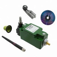
WGLA1A01AA1A
Description
SW ROTARY STNDRD W/NYLON ROLLER
Manufacturer
Honeywell Sensing and Control
Series
WGLAr
Specifications of WGLA1A01AA1A
Circuit
SPDT
Switch Function
On-Mom
Actuator Type
Side Rotary
Mounting Type
Panel Mount, Wireless
Termination Style
Antenna, 2.4 GHz Radio
Actuator Style
Side Rotary
Operating Force Max
9.7N
Contact Voltage Dc Max
3.6V
Lead Free Status / RoHS Status
Lead free / RoHS Compliant
Contact Rating @ Voltage
-
Operating Force
-
Lead Free Status / RoHS Status
Lead free / RoHS Compliant, Lead free / RoHS Compliant
Other names
480-3318


Limitless™ WGLA Series
6.5 Environment Usage/Concerns
6.5.1 Choosing an Antenna/Cable to Meet Application Exposure Conditions
There is no antenna or cable design impervious to every environmental condition that it could be exposed to. So it is
suggested that the application environment be reviewed as follows:
Step 1
Step 2
Step 3
Step 4
In the end, the antenna/cable choice may need to be tested in the actual application conditions to prove suitability.
6.5.2 Outdoor Antenna Installations - Lightning Concerns
Outdoor antenna installations can lead to the possible damage caused by nearby lightning strikes that induce
charges or surges on the antenna and/or antenna extension cables.
A lightning arrestor such as the AL-NFNFB-9 from Hyperlink Technologies can be reviewed against application
requirements.
28
Honeywell Sensing and Control
ATTENTION
National, local and/or regulatory agencies may require the use of a lightning arrestor and possibly
other requirements for an antenna system installation. It is recommended that the customer review
and adhere to these requirements.
Determine where the antenna will be installed and the application conditions: indoor, outdoor, or limited
outdoor exposure. Even if the antenna is going to be used indoors, an outdoor antenna may be more
suitable (i.e., resistant to fluids, rigid construction, etc.)
Determine what the antenna may be subjected to (i.e., fluids, chemicals, oils, wind, shock, vibration, etc.)
The WGLA’s enclosure is designed to meet IP and NEMA seal requirements; however, this step may be
required to provide an extra level of protection, especially if the application may be subjecting antennas
and cables to liquids. The RP-SMA connections, tilt/swivel joints, and cable entrances are potential leak
paths that could lead to corrosion. The following procedure is one way to provide extra protection to these
connections and joints.
Ensure that the area applying tape to is clean from contaminants by first cleaning with mild
detergent/water and completely dry. Follow with an isopropyl alcohol wipe of the area.
Layer 1: Wrap a layer of polyvinyl chloride insulating tape
Layer 2: Wrap a layer of Rubber splicing tape i.e. Scotch™ 23
Layer 3: Wrap a layer of UV stable polyvinyl chloride insulating tape
Layer 1 allows the user to remove Layer 2 for connector inspection, antenna replacement,
repositioning of the tilt/swivel antenna, etc.
A. Review antenna and/or cable materials (listed in Section 6.1) against resistance to chemicals and
B. If shock, vibration, wind, rain, sleet/snow, etc. are in the application, choose an antenna rated for
fluids. If choosing an adhesive mount, adhesive resistance testing may be necessary.
outdoors and has a rigid design as defined in Sections 6.1 and 6.2.3.2.
Issue 2
50051863
Related parts for WGLA1A01AA1A
Image
Part Number
Description
Manufacturer
Datasheet
Request
R

Part Number:
Description:
SERIES 942 SEPARATE COMPLETE SENSOR WITH HEAD AND CONTROL BOX, 3000 MM [118.0 IN] SCAN DISTANCE, TWO ANALOG OUTPUTS (0 VDC TO 10 VDC AND 4 MA TO 20 MA) , TWO SWITCHING OUTPUTS PNP AND DIGITAL LINK
Manufacturer:
Honeywell Sensing and Control
Part Number:
Description:
SERIES 942 SEPARATE COMPLETE SENSOR WITH HEAD AND CONTROL BOX, 900 MM [35.0 IN] SCAN DISTANCE, TWO ANALOG OUTPUTS (0 VDC TO 10 VDC AND 4 MA TO 20 MA) , TWO SWITCHING OUTPUTS PNP AND DIGITAL LINK
Manufacturer:
Honeywell Sensing and Control
Part Number:
Description:
SERIES 942 SEPARATE COMPLETE SENSOR WITH HEAD AND CONTROL BOX, 1500 MM [59.0 IN] SCAN DISTANCE, TWO ANALOG OUTPUTS (0 VDC TO 10 VDC AND 4 MA TO 20 MA) , TWO SWITCHING OUTPUTS PNP AND DIGITAL LINK
Manufacturer:
Honeywell Sensing and Control
Part Number:
Description:
SERIES 942 SEPARATE CONTROL BOX, 3000 MM [118.0 IN] SCAN DISTANCE, TWO ANALOG OUTPUTS (0 VDC TO 10 VDC AND 4 MA TO 20 MA) , TWO SWITCHING OUTPUTS PNP AND DIGITAL LINK, TO USE WITH 942 OR 947 SENSOR HE
Manufacturer:
Honeywell Sensing and Control
Part Number:
Description:
100FW SERIES, SHIELDED 3-WIRE DC SINKING (NPN), N.O. PROXIMITY SENSOR, 0.625 IN CYLINDRICAL HOUSING , 20 GA, MIL-W-16878/4 WIRE. NOMINAL SENSING DISTANCE OF 2,41 MM ±
Manufacturer:
Honeywell Sensing and Control
Part Number:
Description:
100FW SERIES, SHIELDED 3-WIRE DC SINKING (NPN), N.O. PROXIMITY SENSOR, 0.625 IN CYLINDRICAL HOUSING , CONNECTOR VERSION MATES WITH MS3116-10-6S. NOMINAL SENSING DISTANCE OF 2,41 MM ±
Manufacturer:
Honeywell Sensing and Control
Part Number:
Description:
HyCal Sensing Products
Manufacturer:
Honeywell Sensing and Control
Part Number:
Description:
200FW SERIES, SHIELDED 3-WIRE DC SINKING (NPN), N.O. PROXIMITY SENSOR, 0.625 IN CYLINDRICAL HOUSING , CONNECTOR VERSION MATES WITH MS3116-8-4S. NOMINAL SENSING DISTANCE OF 2,4 MM TO 11,4 MM [.09 IN
Manufacturer:
Honeywell Sensing and Control
Part Number:
Description:
FF-SRL SERIES, PRESENCE SENSING DEVICE INITIATION MODULE, 24 VDC
Manufacturer:
Honeywell Sensing and Control
Part Number:
Description:
HyCal Sensing Products
Manufacturer:
Honeywell Sensing and Control
Part Number:
Description:
HyCal Sensing Products
Manufacturer:
Honeywell Sensing and Control
Part Number:
Description:
HyCal Sensing Products
Manufacturer:
Honeywell Sensing and Control
Part Number:
Description:
SERIES 942 SEPARATE SENSOR HEAD, 1500 MM [59.0 IN] SCAN DISTANCE, STAINLESS STEEL M30, CONNECTOR, TO USE WITH 942-M0A CONTROL BOX
Manufacturer:
Honeywell Sensing and Control