WGLA1A01AA1A Honeywell Sensing and Control, WGLA1A01AA1A Datasheet - Page 24
WGLA1A01AA1A
Manufacturer Part Number
WGLA1A01AA1A
Description
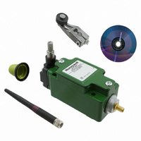
SW ROTARY STNDRD W/NYLON ROLLER
Manufacturer
Honeywell Sensing and Control
Series
WGLAr
Specifications of WGLA1A01AA1A
Circuit
SPDT
Switch Function
On-Mom
Actuator Type
Side Rotary
Mounting Type
Panel Mount, Wireless
Termination Style
Antenna, 2.4 GHz Radio
Actuator Style
Side Rotary
Operating Force Max
9.7N
Contact Voltage Dc Max
3.6V
Lead Free Status / RoHS Status
Lead free / RoHS Compliant
Contact Rating @ Voltage
-
Operating Force
-
Lead Free Status / RoHS Status
Lead free / RoHS Compliant, Lead free / RoHS Compliant
Other names
480-3318


Limitless™ WGLA Series
6.1.1 Omni-directional Antenna Design
The omni-directional antennas offered in the Limitless™ Series were chosen for their ability to be used in
applications where transmit-and-receiver antennas may be moving with respect to each other or could also be
stationary. They are dipole antennas that radiate power (power from the internal radio of the WGLA switch) in a
360° outward pattern in a plane perpendicular to the length of the antenna element. “Omni” may suggest the
antenna radiates power in all directions, but that is not the case. The actual antenna radiation pattern looks more
like a toroid (doughnut-shape) as shown in Figure 10.
Figure 10. Radiation Pattern of an Omni-directional Antenna
Toroid Radiation Pattern -
Pattern is 360 degrees in the vertical
plane, but not the horizontal plane
The antenna radiates virtually zero power in the Z axis and most of the power in the X and Y axis. Increasing the
antenna’s gain will increase the power only in the X and Y axis. As a result, the radiation pattern becomes more
narrow. For instance, this is analogous to the reflector in an automobile’s headlight. The reflector does not add light
or increase the luminous intensity of the light bulb, rather it simply directs all the light energy in the forward direction
where the light is needed most.
20
The WGLA must be installed in accordance with the requirements specified in this document. See Section 3
and Section 4 for EIRP requirements. Only the specified EIRP power settings, antenna types and gains, and
cable lengths (attenuation) as outlined in this document are valid for Limitless™ WGLA Series installations.
Honeywell Sensing and Control
WARNING
ATTENTION
The antenna cables should not be modified (i.e. cut short and/or re-terminated) as it may affect
Communication Agency approval.
2.2 dBi RF Antenna Pattern -
Horizontal
2.2 dBi RF Antenna Pattern -
Vertical
Issue 2
50051863
Related parts for WGLA1A01AA1A
Image
Part Number
Description
Manufacturer
Datasheet
Request
R

Part Number:
Description:
SERIES 942 SEPARATE COMPLETE SENSOR WITH HEAD AND CONTROL BOX, 3000 MM [118.0 IN] SCAN DISTANCE, TWO ANALOG OUTPUTS (0 VDC TO 10 VDC AND 4 MA TO 20 MA) , TWO SWITCHING OUTPUTS PNP AND DIGITAL LINK
Manufacturer:
Honeywell Sensing and Control
Part Number:
Description:
SERIES 942 SEPARATE COMPLETE SENSOR WITH HEAD AND CONTROL BOX, 900 MM [35.0 IN] SCAN DISTANCE, TWO ANALOG OUTPUTS (0 VDC TO 10 VDC AND 4 MA TO 20 MA) , TWO SWITCHING OUTPUTS PNP AND DIGITAL LINK
Manufacturer:
Honeywell Sensing and Control
Part Number:
Description:
SERIES 942 SEPARATE COMPLETE SENSOR WITH HEAD AND CONTROL BOX, 1500 MM [59.0 IN] SCAN DISTANCE, TWO ANALOG OUTPUTS (0 VDC TO 10 VDC AND 4 MA TO 20 MA) , TWO SWITCHING OUTPUTS PNP AND DIGITAL LINK
Manufacturer:
Honeywell Sensing and Control
Part Number:
Description:
SERIES 942 SEPARATE CONTROL BOX, 3000 MM [118.0 IN] SCAN DISTANCE, TWO ANALOG OUTPUTS (0 VDC TO 10 VDC AND 4 MA TO 20 MA) , TWO SWITCHING OUTPUTS PNP AND DIGITAL LINK, TO USE WITH 942 OR 947 SENSOR HE
Manufacturer:
Honeywell Sensing and Control
Part Number:
Description:
100FW SERIES, SHIELDED 3-WIRE DC SINKING (NPN), N.O. PROXIMITY SENSOR, 0.625 IN CYLINDRICAL HOUSING , 20 GA, MIL-W-16878/4 WIRE. NOMINAL SENSING DISTANCE OF 2,41 MM ±
Manufacturer:
Honeywell Sensing and Control
Part Number:
Description:
100FW SERIES, SHIELDED 3-WIRE DC SINKING (NPN), N.O. PROXIMITY SENSOR, 0.625 IN CYLINDRICAL HOUSING , CONNECTOR VERSION MATES WITH MS3116-10-6S. NOMINAL SENSING DISTANCE OF 2,41 MM ±
Manufacturer:
Honeywell Sensing and Control
Part Number:
Description:
HyCal Sensing Products
Manufacturer:
Honeywell Sensing and Control
Part Number:
Description:
200FW SERIES, SHIELDED 3-WIRE DC SINKING (NPN), N.O. PROXIMITY SENSOR, 0.625 IN CYLINDRICAL HOUSING , CONNECTOR VERSION MATES WITH MS3116-8-4S. NOMINAL SENSING DISTANCE OF 2,4 MM TO 11,4 MM [.09 IN
Manufacturer:
Honeywell Sensing and Control
Part Number:
Description:
FF-SRL SERIES, PRESENCE SENSING DEVICE INITIATION MODULE, 24 VDC
Manufacturer:
Honeywell Sensing and Control
Part Number:
Description:
HyCal Sensing Products
Manufacturer:
Honeywell Sensing and Control
Part Number:
Description:
HyCal Sensing Products
Manufacturer:
Honeywell Sensing and Control
Part Number:
Description:
HyCal Sensing Products
Manufacturer:
Honeywell Sensing and Control
Part Number:
Description:
SERIES 942 SEPARATE SENSOR HEAD, 1500 MM [59.0 IN] SCAN DISTANCE, STAINLESS STEEL M30, CONNECTOR, TO USE WITH 942-M0A CONTROL BOX
Manufacturer:
Honeywell Sensing and Control