WGLA1A01AA1A Honeywell Sensing and Control, WGLA1A01AA1A Datasheet - Page 30
WGLA1A01AA1A
Manufacturer Part Number
WGLA1A01AA1A
Description
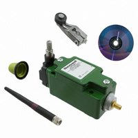
SW ROTARY STNDRD W/NYLON ROLLER
Manufacturer
Honeywell Sensing and Control
Series
WGLAr
Specifications of WGLA1A01AA1A
Circuit
SPDT
Switch Function
On-Mom
Actuator Type
Side Rotary
Mounting Type
Panel Mount, Wireless
Termination Style
Antenna, 2.4 GHz Radio
Actuator Style
Side Rotary
Operating Force Max
9.7N
Contact Voltage Dc Max
3.6V
Lead Free Status / RoHS Status
Lead free / RoHS Compliant
Contact Rating @ Voltage
-
Operating Force
-
Lead Free Status / RoHS Status
Lead free / RoHS Compliant, Lead free / RoHS Compliant
Other names
480-3318


Limitless™ WGLA Series
Magnetic mount: The benefit of the magnetic-mount antenna is its
ability to mount on any ferrous-metal surface and in various
orientations. A smooth metal surface is preferred to allow the best
attraction of the magnet to the surface. First, the user will need to
determine if the magnetic attraction is sufficient to hold the antenna in
the desired position (i.e., shock, vibration, etc. in the application).
Placing the antenna in a location where it cannot be inadvertently
displaced may help. Magnetic-mount antennas are not designed for
mobile applications.
6.2.4 Antenna Adjustment Considerations
The antenna of the WGLA switch and WPMM monitor should be
oriented in parallel. This will, in most cases, allow the longest range
and highest RF signal. The least RF signal is normally in a direction in-
line with the top of the antenna, so avoid having antennas pointed
directly toward or directly away from each other.
Figure 22. Highest RF signal when antennas are as parallel to each other as possible
6.3
The signal range is defined as the physical distance between the WGLA switch and WPMM monitor. It’s a function
of the antenna’s gain, radio output of the WGLA switch and WPMM monitor (8 dBm or 18 dBm), and cable loss (if
used) in conjunction with the environment (i.e. outdoor urban, indoors, etc.) that the Limitless™ product is operating
in. The Honeywell antenna range calculator can be used to estimate the expected signal range that can be achieved
between the WGLA switch and WPMM monitor with chosen antennas, cable extensions, radio output, etc. The
calculator can be found at www.honeywell.com/limitless.
Signal range specification:
250 m [820 ft] (nominal) – 8 dBm radio output
305 m [1000 ft] (nominal) – 18 dBm radio output
Line of sight with a 2.2 dBi antenna installed on the WGLA switch and WPMM monitor
26
Honeywell Sensing and Control
Signal Range of an Antenna
Figure 21. Magnetic Mount Bracket
with Antenna – Mounted on Steel
Surface
Issue 2
50051863
Related parts for WGLA1A01AA1A
Image
Part Number
Description
Manufacturer
Datasheet
Request
R

Part Number:
Description:
SERIES 942 SEPARATE COMPLETE SENSOR WITH HEAD AND CONTROL BOX, 3000 MM [118.0 IN] SCAN DISTANCE, TWO ANALOG OUTPUTS (0 VDC TO 10 VDC AND 4 MA TO 20 MA) , TWO SWITCHING OUTPUTS PNP AND DIGITAL LINK
Manufacturer:
Honeywell Sensing and Control
Part Number:
Description:
SERIES 942 SEPARATE COMPLETE SENSOR WITH HEAD AND CONTROL BOX, 900 MM [35.0 IN] SCAN DISTANCE, TWO ANALOG OUTPUTS (0 VDC TO 10 VDC AND 4 MA TO 20 MA) , TWO SWITCHING OUTPUTS PNP AND DIGITAL LINK
Manufacturer:
Honeywell Sensing and Control
Part Number:
Description:
SERIES 942 SEPARATE COMPLETE SENSOR WITH HEAD AND CONTROL BOX, 1500 MM [59.0 IN] SCAN DISTANCE, TWO ANALOG OUTPUTS (0 VDC TO 10 VDC AND 4 MA TO 20 MA) , TWO SWITCHING OUTPUTS PNP AND DIGITAL LINK
Manufacturer:
Honeywell Sensing and Control
Part Number:
Description:
SERIES 942 SEPARATE CONTROL BOX, 3000 MM [118.0 IN] SCAN DISTANCE, TWO ANALOG OUTPUTS (0 VDC TO 10 VDC AND 4 MA TO 20 MA) , TWO SWITCHING OUTPUTS PNP AND DIGITAL LINK, TO USE WITH 942 OR 947 SENSOR HE
Manufacturer:
Honeywell Sensing and Control
Part Number:
Description:
100FW SERIES, SHIELDED 3-WIRE DC SINKING (NPN), N.O. PROXIMITY SENSOR, 0.625 IN CYLINDRICAL HOUSING , 20 GA, MIL-W-16878/4 WIRE. NOMINAL SENSING DISTANCE OF 2,41 MM ±
Manufacturer:
Honeywell Sensing and Control
Part Number:
Description:
100FW SERIES, SHIELDED 3-WIRE DC SINKING (NPN), N.O. PROXIMITY SENSOR, 0.625 IN CYLINDRICAL HOUSING , CONNECTOR VERSION MATES WITH MS3116-10-6S. NOMINAL SENSING DISTANCE OF 2,41 MM ±
Manufacturer:
Honeywell Sensing and Control
Part Number:
Description:
HyCal Sensing Products
Manufacturer:
Honeywell Sensing and Control
Part Number:
Description:
200FW SERIES, SHIELDED 3-WIRE DC SINKING (NPN), N.O. PROXIMITY SENSOR, 0.625 IN CYLINDRICAL HOUSING , CONNECTOR VERSION MATES WITH MS3116-8-4S. NOMINAL SENSING DISTANCE OF 2,4 MM TO 11,4 MM [.09 IN
Manufacturer:
Honeywell Sensing and Control
Part Number:
Description:
FF-SRL SERIES, PRESENCE SENSING DEVICE INITIATION MODULE, 24 VDC
Manufacturer:
Honeywell Sensing and Control
Part Number:
Description:
HyCal Sensing Products
Manufacturer:
Honeywell Sensing and Control
Part Number:
Description:
HyCal Sensing Products
Manufacturer:
Honeywell Sensing and Control
Part Number:
Description:
HyCal Sensing Products
Manufacturer:
Honeywell Sensing and Control
Part Number:
Description:
SERIES 942 SEPARATE SENSOR HEAD, 1500 MM [59.0 IN] SCAN DISTANCE, STAINLESS STEEL M30, CONNECTOR, TO USE WITH 942-M0A CONTROL BOX
Manufacturer:
Honeywell Sensing and Control