WGLA1A01AA1A Honeywell Sensing and Control, WGLA1A01AA1A Datasheet - Page 27
WGLA1A01AA1A
Manufacturer Part Number
WGLA1A01AA1A
Description
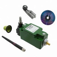
SW ROTARY STNDRD W/NYLON ROLLER
Manufacturer
Honeywell Sensing and Control
Series
WGLAr
Specifications of WGLA1A01AA1A
Circuit
SPDT
Switch Function
On-Mom
Actuator Type
Side Rotary
Mounting Type
Panel Mount, Wireless
Termination Style
Antenna, 2.4 GHz Radio
Actuator Style
Side Rotary
Operating Force Max
9.7N
Contact Voltage Dc Max
3.6V
Lead Free Status / RoHS Status
Lead free / RoHS Compliant
Contact Rating @ Voltage
-
Operating Force
-
Lead Free Status / RoHS Status
Lead free / RoHS Compliant, Lead free / RoHS Compliant
Other names
480-3318


Limitless™ WGLA Series
6.2.3 Antenna Connection, Styles, and Mounting Options
6.2.3.1 Antenna Connection, Styles, and Mounting Options
Physical connection of the antenna to the WGLA switch is accomplished by using mating RP-SMA connectors: plug
and jack. Integral-mount antennas have an RP-SMA plug that connects directly to the WGLA RP-SMA jack. The
remote mount antenna uses a cable with a RP-SMA plug that connects directly to the WGLA RP-SMA jack allowing
the antenna to be remotely mounted away from the WGLA switch. Mounting options are based on user preference,
communication agency approvals, WGLA switch mounting location, and obstacles as discussed in Section 6.2.1.
An integral or remote mount antenna can be easily mounted by threading the mating RP-SMA plug of the
antenna to the RP-SMA jack on the WGLA switch. Reference section 6.5 for further details on extra environmental
protection of RP-SMA connections. Tighten the RP-SMA connection until finger tight, and then attach the lime/black
guard finger tight. See Figures 13 and 14.
Figure 13. Limitless™ WGLA RP-SMA Connection,
Integral
6.2.3.2 Antenna Styles and Mounting Options
Choosing an antenna mounting style depends on application conditions, along with antenna benefits and/or features
and user preference. The antenna’s gain (discussed further in Section 6.4) to some extent determines physical size;
also a consideration is the amount of room available in the application.
Straight or Tilt/Swivel: A benefit of the straight antenna is its rigid design and resistance to being repositioned
(shock, vibration, wind, etc.) when compared to a tilt and swivel design. It is also more resistant to weather
conditions as there’s no swivel-joint connection for contaminants to enter. A benefit of the tilt & swivel design is that
it allows easier positioning in relation to other antenna(s) to obtain a suitable RF signal.
Failure to comply with these instructions could result in death or serious injury.
CAUTION
RF EXPOSURE
To satisfy FCC RF exposure requirements for mobile transmitting devices, a separation distance of 20 cm
[7.87 in] or more should be maintained between the antenna of this device and persons during device
operation. To ensure compliance, operation at closer than this distance is not recommended. The antenna
used for this transmission must not be co-located in conjunction with any other antenna or transmitter.
Power to the WGLA switch should not be applied during installation of an antenna as damage could occur to
the WGLA switch electronics.
WARNING
Figure 14. Limitless™ WGLA RP-SMA Connection,
Remote
Honeywell Sensing and Control 23
Issue 2
50051863
Related parts for WGLA1A01AA1A
Image
Part Number
Description
Manufacturer
Datasheet
Request
R

Part Number:
Description:
SERIES 942 SEPARATE COMPLETE SENSOR WITH HEAD AND CONTROL BOX, 3000 MM [118.0 IN] SCAN DISTANCE, TWO ANALOG OUTPUTS (0 VDC TO 10 VDC AND 4 MA TO 20 MA) , TWO SWITCHING OUTPUTS PNP AND DIGITAL LINK
Manufacturer:
Honeywell Sensing and Control
Part Number:
Description:
SERIES 942 SEPARATE COMPLETE SENSOR WITH HEAD AND CONTROL BOX, 900 MM [35.0 IN] SCAN DISTANCE, TWO ANALOG OUTPUTS (0 VDC TO 10 VDC AND 4 MA TO 20 MA) , TWO SWITCHING OUTPUTS PNP AND DIGITAL LINK
Manufacturer:
Honeywell Sensing and Control
Part Number:
Description:
SERIES 942 SEPARATE COMPLETE SENSOR WITH HEAD AND CONTROL BOX, 1500 MM [59.0 IN] SCAN DISTANCE, TWO ANALOG OUTPUTS (0 VDC TO 10 VDC AND 4 MA TO 20 MA) , TWO SWITCHING OUTPUTS PNP AND DIGITAL LINK
Manufacturer:
Honeywell Sensing and Control
Part Number:
Description:
SERIES 942 SEPARATE CONTROL BOX, 3000 MM [118.0 IN] SCAN DISTANCE, TWO ANALOG OUTPUTS (0 VDC TO 10 VDC AND 4 MA TO 20 MA) , TWO SWITCHING OUTPUTS PNP AND DIGITAL LINK, TO USE WITH 942 OR 947 SENSOR HE
Manufacturer:
Honeywell Sensing and Control
Part Number:
Description:
100FW SERIES, SHIELDED 3-WIRE DC SINKING (NPN), N.O. PROXIMITY SENSOR, 0.625 IN CYLINDRICAL HOUSING , 20 GA, MIL-W-16878/4 WIRE. NOMINAL SENSING DISTANCE OF 2,41 MM ±
Manufacturer:
Honeywell Sensing and Control
Part Number:
Description:
100FW SERIES, SHIELDED 3-WIRE DC SINKING (NPN), N.O. PROXIMITY SENSOR, 0.625 IN CYLINDRICAL HOUSING , CONNECTOR VERSION MATES WITH MS3116-10-6S. NOMINAL SENSING DISTANCE OF 2,41 MM ±
Manufacturer:
Honeywell Sensing and Control
Part Number:
Description:
HyCal Sensing Products
Manufacturer:
Honeywell Sensing and Control
Part Number:
Description:
200FW SERIES, SHIELDED 3-WIRE DC SINKING (NPN), N.O. PROXIMITY SENSOR, 0.625 IN CYLINDRICAL HOUSING , CONNECTOR VERSION MATES WITH MS3116-8-4S. NOMINAL SENSING DISTANCE OF 2,4 MM TO 11,4 MM [.09 IN
Manufacturer:
Honeywell Sensing and Control
Part Number:
Description:
FF-SRL SERIES, PRESENCE SENSING DEVICE INITIATION MODULE, 24 VDC
Manufacturer:
Honeywell Sensing and Control
Part Number:
Description:
HyCal Sensing Products
Manufacturer:
Honeywell Sensing and Control
Part Number:
Description:
HyCal Sensing Products
Manufacturer:
Honeywell Sensing and Control
Part Number:
Description:
HyCal Sensing Products
Manufacturer:
Honeywell Sensing and Control
Part Number:
Description:
SERIES 942 SEPARATE SENSOR HEAD, 1500 MM [59.0 IN] SCAN DISTANCE, STAINLESS STEEL M30, CONNECTOR, TO USE WITH 942-M0A CONTROL BOX
Manufacturer:
Honeywell Sensing and Control