STGIPS10K60A STMicroelectronics, STGIPS10K60A Datasheet - Page 5
STGIPS10K60A
Manufacturer Part Number
STGIPS10K60A
Description
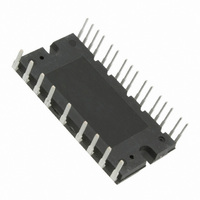
MOD IPM 600V 10A 25-SDIP
Manufacturer
STMicroelectronics
Type
IGBTr
Specifications of STGIPS10K60A
Configuration
3 Phase
Current
10A
Voltage
600V
Voltage - Isolation
2500VDC
Package / Case
PCB Module
Module Configuration
3-Phase Bridge
Transistor Polarity
N Channel
Dc Collector Current
10A
Collector Emitter Voltage Vces
600V
Power Dissipation Pd
33W
Operating Temperature Range
-40°C To
Rohs Compliant
Yes
Collector-emitter Saturation Voltage
2.1 V
Continuous Collector Current At 25 C
10 A
Power Dissipation
26 W
Maximum Operating Temperature
+ 125 C
Minimum Operating Temperature
- 40 C
Mounting Style
Through Hole
Operating Temperature (max)
125C
Operating Temperature (min)
-40C
Pin Count
25
Mounting
Through Hole
Screening Level
Automotive
For Use With
497-10836 - POWER BOARD STGIPS10K60A
Lead Free Status / RoHS Status
Lead free / RoHS Compliant
Other names
497-10404-5
Available stocks
Company
Part Number
Manufacturer
Quantity
Price

Part Number:
STGIPS10K60A
Manufacturer:
ST
Quantity:
20 000


STGIPS10K60A
2
2.1
Electrical ratings
Absolute maximum ratings
Table 3.
1. Applied between
2. Calculated according to the iterative formula:
3. Pulse width limited by max junction temperature.
Table 4.
V
Symbol
Symbol
± I
dV
PN(surge)
± I
V
V
V
P
V
V
t
V
CP
OUT
out
scw
CES
boot
TOT
CC
PN
C
IN
(2)
/dt
(3)
Output voltage applied between OUT
OUT
Low voltage power supply
Bootstrap voltage applied between V
for i = U, V, W
Logic input voltage applied between HIN
and GND for i = U, V, W
Allowed output slew rate
Supply voltage applied between P - N
Supply voltage (surge) applied between P - N
N
Each IGBT collector emitter voltage (V
Each IGBT continuous collector current at
T
Each IGBT pulsed collector current
Each IGBT total dissipation at T
Short-circuit withstand time, V
T
Inverter part
Control part
C
j
V
= 125 °C, V
, N
= 25°C
W
W
HIN
- GND (V
i
, LIN
I
C
CC
(
i
T
and GND for i = U, V, W.
CC
C
= V
)
Parameter
Parameter
= 15 V)
=
Doc ID 15587 Rev 7
boot
-------------------------------------------------------------------------------------------------------
R
= 15 V, V
thj c
–
×
CE
V
C
= 0.5 V
CE sat
IN
= 25°C
(1)
(
T
boot i
U,
U
j max
= 5 V
(
IN
, N
) max
OUT
(
(1)
i
(BR)CES
, LIN
- OUT
V
, N
)
= 0)
–
V,
)
(
i
U
T
W
T
,
C
j max
i
(
)
,
I
C
(
-0.3 to V
T
-3 to V
C
-0.3 to +18
)
-1 to 618
)
Value
Value
450
500
600
50
10
20
33
5
boot
CC
Electrical ratings
+0.3
-18
Unit
V/ns
Unit
µs
W
V
V
V
V
V
V
V
A
A
5/18
Related parts for STGIPS10K60A
Image
Part Number
Description
Manufacturer
Datasheet
Request
R

Part Number:
Description:
STMicroelectronics [RIPPLE-CARRY BINARY COUNTER/DIVIDERS]
Manufacturer:
STMicroelectronics
Datasheet:
Part Number:
Description:
STMicroelectronics [LIQUID-CRYSTAL DISPLAY DRIVERS]
Manufacturer:
STMicroelectronics
Datasheet:

Part Number:
Description:
BOARD EVAL FOR MEMS SENSORS
Manufacturer:
STMicroelectronics
Datasheet:
Part Number:
Description:
NPN TRANSISTOR POWER MODULE
Manufacturer:
STMicroelectronics
Datasheet:
Part Number:
Description:
TURBOSWITCH ULTRA-FAST HIGH VOLTAGE DIODE
Manufacturer:
STMicroelectronics
Datasheet:
Part Number:
Description:
Manufacturer:
STMicroelectronics
Datasheet:
Part Number:
Description:
DIODE / SCR MODULE
Manufacturer:
STMicroelectronics
Datasheet:
Part Number:
Description:
DIODE / SCR MODULE
Manufacturer:
STMicroelectronics
Datasheet:
Part Number:
Description:
Search -----> STE16N100
Manufacturer:
STMicroelectronics
Datasheet:
Part Number:
Description:
Search ---> STE53NA50
Manufacturer:
STMicroelectronics
Datasheet:
Part Number:
Description:
NPN Transistor Power Module
Manufacturer:
STMicroelectronics
Datasheet:
Part Number:
Description:
DIODE / SCR MODULE
Manufacturer:
STMicroelectronics
Datasheet: