GA400TD25S Vishay, GA400TD25S Datasheet - Page 3
GA400TD25S
Manufacturer Part Number
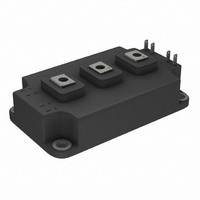
GA400TD25S
Description
IGBT FAST 250V 400A INT-A-PAK
Manufacturer
Vishay
Datasheet
1.GA400TD25S.pdf
(10 pages)
Specifications of GA400TD25S
Configuration
Half Bridge
Voltage - Collector Emitter Breakdown (max)
250V
Vce(on) (max) @ Vge, Ic
1.6V @ 15V, 400A
Current - Collector (ic) (max)
400A
Current - Collector Cutoff (max)
500µA
Input Capacitance (cies) @ Vce
36nF @ 30V
Power - Max
1350W
Input
Standard
Ntc Thermistor
No
Mounting Type
Chassis Mount
Package / Case
Dual INT-A-PAK (3 + 8)
Collector- Emitter Voltage Vceo Max
250 V
Continuous Collector Current At 25 C
400 A
Maximum Operating Temperature
+ 150 C
Maximum Gate Emitter Voltage
+/- 20 V
Minimum Operating Temperature
- 40 C
Mounting Style
Screw
Lead Free Status / RoHS Status
Contains lead / RoHS non-compliant
Igbt Type
-
Lead Free Status / RoHS Status
Contains lead / RoHS non-compliant, Lead free / RoHS Compliant
Other names
*GA400TD25S
VS-GA400TD25S
VS-GA400TD25S
VSGA400TD25S
VSGA400TD25S
VS-GA400TD25S
VS-GA400TD25S
VSGA400TD25S
VSGA400TD25S
Available stocks
Company
Part Number
Manufacturer
Quantity
Price
Company:

Part Number:
GA400TD25S
Manufacturer:
SANYO
Quantity:
2 100
Part Number:
GA400TD25S
Quantity:
57
Company:
Part Number:
GA400TD25S-703058
Manufacturer:
SEMIKRON
Quantity:
492


www.irf.com
1000
100
3 0 0
2 0 0
1 0 0
0
Fig. 2 - Typical Output Characteristics
1.0
0.1
T = 150 C
J
125°C
V
CE
T = 25 C
o
J
, Collector-to-Emitter Voltage (V)
S q u a re w a v e :
o
6 0 % o f ra te d
Id eal diod es
1.5
v o lta g e
Fig. 1 - Typical Load Current vs. Frequency
80µs
V
20µs PULSE WIDTH
GE
= 15V
(Load Current = I
1
f, Frequency (kHz)
2.0
RMS
1000
of fundamental)
100
Fig. 3 - Typical Transfer Characteristics
10
5
T = 150 C
J
V
GE
1 0
125°C
, Gate-to-Emitter Voltage (V)
o
GA400TD25S
6
D u ty c y c le : 5 0 %
T = 1 2 5 ° C
T
G a te d riv e a s s p e c ifie d
P o w e r D is s ip a tio n = 1 8 4 W
J
sink
T = 25 C
J
80µs
= 9 0 ° C
V
5µs PULSE WIDTH
CE
CC
7
o
= 50V
25V
3
1 0 0
8
A
Related parts for GA400TD25S
Image
Part Number
Description
Manufacturer
Datasheet
Request
R

Part Number:
Description:
Power Inductors
Manufacturer:
Gowanda Electronics
Datasheet:

Part Number:
Description:
357-036-542-201 CARDEDGE 36POS DL .156 BLK LOPRO
Manufacturer:
Vishay
Datasheet:
Part Number:
Description:
357-036-542-201 CARDEDGE 36POS DL .156 BLK LOPRO
Manufacturer:
Vishay
Datasheet:
Part Number:
Description:
357-036-542-201 CARDEDGE 36POS DL .156 BLK LOPRO
Manufacturer:
Vishay
Datasheet:
Part Number:
Description:
357-036-542-201 CARDEDGE 36POS DL .156 BLK LOPRO
Manufacturer:
Vishay
Datasheet:
Part Number:
Description:
357-036-542-201 CARDEDGE 36POS DL .156 BLK LOPRO
Manufacturer:
Vishay
Datasheet:
Part Number:
Description:
357-036-542-201 CARDEDGE 36POS DL .156 BLK LOPRO
Manufacturer:
Vishay
Datasheet:
Part Number:
Description:
357-036-542-201 CARDEDGE 36POS DL .156 BLK LOPRO
Manufacturer:
Vishay
Datasheet:
Part Number:
Description:
357-036-542-201 CARDEDGE 36POS DL .156 BLK LOPRO
Manufacturer:
Vishay
Datasheet:
Part Number:
Description:
357-036-542-201 CARDEDGE 36POS DL .156 BLK LOPRO
Manufacturer:
Vishay
Datasheet:
Part Number:
Description:
357-036-542-201 CARDEDGE 36POS DL .156 BLK LOPRO
Manufacturer:
Vishay
Datasheet:
Part Number:
Description:
357-036-542-201 CARDEDGE 36POS DL .156 BLK LOPRO
Manufacturer:
Vishay
Datasheet:
Part Number:
Description:
357-036-542-201 CARDEDGE 36POS DL .156 BLK LOPRO
Manufacturer:
Vishay
Datasheet:
Part Number:
Description:
357-036-542-201 CARDEDGE 36POS DL .156 BLK LOPRO
Manufacturer:
Vishay
Datasheet:
Part Number:
Description:
357-036-542-201 CARDEDGE 36POS DL .156 BLK LOPRO
Manufacturer:
Vishay
Datasheet: