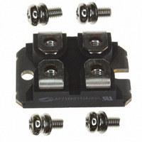
APT100GT120JRDL Microsemi Power Products Group, APT100GT120JRDL Datasheet - Page 5

APT100GT120JRDL
Manufacturer Part Number
APT100GT120JRDL
Description
IGBT 1200V 123A 570W SOT227
Manufacturer
Microsemi Power Products Group
Datasheet
1.APT100GT120JRDL.pdf
(9 pages)
Specifications of APT100GT120JRDL
Igbt Type
NPT
Configuration
Single
Voltage - Collector Emitter Breakdown (max)
1200V
Vce(on) (max) @ Vge, Ic
3.7V @ 15V, 100A
Current - Collector (ic) (max)
123A
Current - Collector Cutoff (max)
300µA
Input Capacitance (cies) @ Vce
6.7nF @ 25V
Power - Max
570W
Input
Standard
Ntc Thermistor
No
Mounting Type
Chassis Mount
Package / Case
ISOTOP
Lead Free Status / RoHS Status
Lead free / RoHS Compliant
Other names
APT100GT120JRDLMI
APT100GT120JRDLMI
APT100GT120JRDLMI
Dissipated Power
Typical Performance Curves
(Watts)
FIGURE 19b, TRANSIENT THERMAL IMPEDANCE MODEL
FIGURE 17, Capacitance vs Collector-To-Emitter Voltage
10000
1000
0.25
0.15
0.05
0. 2
V
0. 1
100
10
CE
0
, COLLECTOR-TO-EMITTER VOLTAGE (VOLTS)
0 100 200 300 400 500 600 700 800 900
10
T
-4
J
Figure 19a, Maximum Effective Transient Thermal Impedance, Junction-To-Case vs Pulse Duration
(°C)
.034
D = 0.9
.045
0.5
0.3
0.05
0.7
0.1
10
.0618
.0135
Z
impedances: Case to sink,
sink to ambient, etc. Set to
zero when modeling only
the case to junction.
-3
EXT
are the external thermal
17.42
RECTANGULAR PULSE DURATION (SECONDS)
.039
T
C
C
C
C
10
(°C)
ies
oes
res
SINGLE PULSE
-2
10
-1
Figure 20, Operating Frequency vs Collector Current
40
30
20
10
0
0
10
I
FIGURE 18, Minimum Switching Safe Operating Area
75°C
0.1
250
200
150
100
C
20 30
, COLLECTOR CURRENT (A)
50
0
100°C
0
V
CE
Note:
200
, COLLECTOR-TO-EMITTER VOLTAGE
40 50
Peak T J = P DM x Z θJC + T C
Duty Factor D =
400
t 1
1
60 70
600
t 2
T
T
D = 50 %
V
R
t 1
J
C
CE
G
80 90 100
800
= 125
/
= 75
= 4.7Ω
t 2
= 800V
APT100GT120JRDL(G)
°
°
C
C
1000 1200 1400
10
F
f
f
P
max1
max2
max
diss
=
= min (f
=
=
t
T
d(on)
P
E
R
J
diss
on2
θJC
- T
max
+ t
- P
+ E
C
0.05
r
cond
, f
+ t
off
max2
d(off)
)
+ t
f


