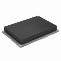
ATZB-24-A2 Atmel, ATZB-24-A2 Datasheet - Page 94

ATZB-24-A2
Manufacturer Part Number
ATZB-24-A2
Description
KIT MOD 802.15.4/ZIGB 2.4GHZ ANT
Manufacturer
Atmel
Specifications of ATZB-24-A2
Frequency
2.4GHz
Data Rate - Maximum
250kbps
Modulation Or Protocol
802.15.4 Zigbee
Applications
Home/Building Automation, Industrial Control and Monitoring
Power - Output
3dBm
Sensitivity
-101dBm
Voltage - Supply
1.8 V ~ 3.6 V
Current - Receiving
19mA
Current - Transmitting
18mA
Data Interface
PCB, Surface Mount
Memory Size
128kBytes Flash, 8kBytes RAM, 4kBytes EEPROM
Antenna Connector
On-Board, Chip
Operating Temperature
-40°C ~ 85°C
Package / Case
Module
Tool Type
Wireless Development Kit
Core Architecture
AVR
Cpu Core
AVR 8
Data Bus Width
8 bit
Description/function
ZigBit 2.4 GHz Dual Chip Antenna
Wireless Frequency
2.4 GHz
Interface Type
UART, I2C, SPI
Operating Voltage
1.8 V to 3.6 V
Output Power
3 dBm
Antenna
Chip Antenna
Operating Temperature Range
- 40 C to + 85 C
Lead Free Status / RoHS Status
Lead free / RoHS Compliant
Available stocks
Company
Part Number
Manufacturer
Quantity
Price
Part Number:
ATZB-24-A2
Manufacturer:
ATMEL/爱特梅尔
Quantity:
20 000
Company:
Part Number:
ATZB-24-A2R
Manufacturer:
CIRRUS
Quantity:
201
8069Q–AVR–12/10
Figure 36-1. Analog Comparator Voltage Scaler vs. Scalefac
3.
4. ADC gain stage output range is limited to 2.4 V
Problem fix/Workaround
Use external voltage input for the analog comparator if accurate voltage levels are needed
ADC has increased INL error for some operating conditions
Some ADC configurations or operating condition will result in increased INL error.
In signed mode INL is increased to:
– 6LSB for sample rates above 1Msps, and up to 8 LSB for 2Msps sample rate.
– 6LSB for reference voltage below 1.1V when VCC is above 3.0V.
– 20LSB for ambient temperature below 0 degree C and reference voltage below 1.3V.
In unsigned mode, the INL error cannot be guaranteed, and this mode should not be used.
Problem fix/Workaround
None, avoid using the ADC in the above configurations in order to prevent increased INL
error. Use the ADC in signed mode also for single ended measurements.
The amplified output of the ADC gain stage will never go above 2.4 V, hence the differential
input will only give correct output when below 2.4 V/gain. For the available gain settings, this
gives a differential input range of:
–
–
–
–
–
–
–
16x
32x
64x
3.5
2.5
1.5
0.5
1x
2x
4x
8x
3
2
1
0
0
T = 25°C
gain:
gain:
gain:
gain:
gain:
gain:
gain:
5
10
300
150
2.4
1.2
0.6
75
38
15
V
V
V
mV
mV
mV
mV
20
25
SCALEFAC
30
35
40
45
50
55
XMEGA A4
60
65
3.3 V
2.7 V
1.8 V
94


