ETRX2 Telegesis Ltd, ETRX2 Datasheet
ETRX2
Specifications of ETRX2


Related parts for ETRX2


ETRX2 Summary of contents
Page 1
... Telegesis ETRX2, ETRX2HR ETRX2 and ETRX2HR ZIGBEE® MODULES ©2009 Telegesis (UK) Ltd PRODUCT MANUAL TG-ETRX2-PM-001-109 Product Manual 1.09 ETRX2 Product Manual (Rev 1.09) ...
Page 2
... AC ELECTRICAL CHARACTERISTICS ............................................................................ 17 12 PHYSICAL DIMENSIONS .................................................................................................. 19 13 SOLDERING TEMPERATURE TIME PROFILE (FOR REFLOW SOLDERING) .............. 20 13.1 For Lead Solder ............................................................................................................... 20 13.2 For Lead-free Solder........................................................................................................ 20 14 PRODUCT LABEL DRAWING ........................................................................................... 21 15 RECOMMENDED FOOTPRINT ......................................................................................... 22 15.1 Example carrier board...................................................................................................... 23 ©2009 Telegesis (UK) Ltd Table of Contents - 2 - ETRX2 Product Manual (Rev 1.09) ETRX2 ...
Page 3
... Component Orientation.................................................................................................... 27 18.3 Reel Dimensions.............................................................................................................. 27 18.4 Packaging ........................................................................................................................ 27 19 ORDERING INFORMATION .............................................................................................. 28 20 TRADEMARKS................................................................................................................... 29 21 DISCLAIMER...................................................................................................................... 29 22 ROHS DECLARATION....................................................................................................... 29 23 DATA SHEET STATUS...................................................................................................... 29 24 LIFE SUPPORT POLICY.................................................................................................... 29 25 RELATED DOCUMENTS ................................................................................................... 30 26 CONTACT INFORMATION ................................................................................................ 30 ©2009 Telegesis (UK) Ltd - 3 - ETRX2 Product Manual (Rev 1.09) ETRX2 ...
Page 4
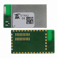
... High sensitivity of -98dBm typ packet error rate • Hardware acceleration for IEEE 802.15.4 compliant transmissions ©2009 Telegesis (UK) Ltd The Telegesis ETRX2 module is a low power 2.4GHz ISM band transceiver based on the Ember EM250 single chip ZigBee®/IEEE802.15.4 solution. It has been designed to be integrated into any device without the need for RF experience and expertise ...
Page 5
... Unexpected start-up in bootloader mode The bootloader which runs on the ETRX2 can be initiated with a firmware command, but it can also be triggered in hardware. If the A/D2 input (pad 10) is pulled low during the boot-up of the module it will enter the bootloader routine, so exercise caution when doing hardware design and ensure that this pin is not grounded during start-up and reset or driven from an analogue voltage that may be sensed as a logic 0 ...
Page 6
... If you require to use a specific external antenna with the ETRX2 module feel free to contact Telegesis about getting your choice of antenna tested to be included in the FCC approvals. 2.1.2 ...
Page 7
... EC-R&TTE Certificated If the ETRX2 module is incorporated into an OEM product, the OEM product manufacturer must ensure compliance of the final product to the European Harmonised EMC, and low voltage/safety standards. A Declaration of Conformity must be issued for each of these standards and kept on file as described in the R&TTE Directive. The final product must not exceed the specified power ratings, antenna specifications and installation requirements as specified in this ETRX2 user manual ...
Page 8
... Ember meshing and self-healing stack, so interoperability with wireless mesh networking solutions from other manufacturers is unlikely when using this default firmware. For more information on ZigBee® compliance and the AT command interface please refer to the latest AT command dictionary and the ETRX2 user guide. ©2009 Telegesis (UK) Ltd - 8 - ETRX2 Product Manual (Rev 1 ...
Page 9
... Module Pinout The ETRX2 is pin compatible with the ETRX1, (NB: it has additional pins to the ETRX1). For all new designs using either ETRX1 or ETRX2 it is recommended that you use the ETRX2 footprint to ensure the option of future upgrading is guaranteed. The table below gives details about the 38 module pin signals for direct SMD soldering of the ETRX2 to the application board ...
Page 10
... GPIO 8 (31) TXD {2} GPIO 9 (32) RXD {2} GPIO 10 (33) GND GND I/O10 GPIO 15 (41) I/O11 GPIO 16 (40) GND GND RXTXSW (11) GND GND GND GND GND GND GND GND N/C {4} GPIO 7 (30) Table 1: Pin Information - 10 - ETRX2 Harwin Pin ETRX2 Product Manual (Rev 1.09) ETRX2 ...
Page 11
... RF transceiver 2.4GHz 16-bit XAP2b µC 16-bit XAP16b uC BALUN 128kB flash / 5k RAM 128kB flash / 5k RAM 24MHz 32,768kHz (optional) Figure 2: Hardware Diagram Depending on the power supply conditions of the application the - 11 - I/O0 – I/O11 A UART RESET RESET 4 SIF programming ETRX2 Product Manual (Rev 1.09) ETRX2 ...
Page 12
... I/O. UART The AT style command interpreter can be accessed via the TXD and RXD pins. The ETRX2 can buffer up to 128 bytes of incoming data in a software FIFO buffer and uses XON/XOFF or hardware flow control. See [2] for more information about the built-in UART. ...
Page 13
... Telegesis user guide. Check www.telegesis.com for updates. Each module comes with a unique 64-bit 802.15.4 identifier which is stored in non-volatile memory. The commands and responses pass through the serial port of the ETRX2 as ASCII text simple terminal application will usually suffice. We provide Telegesis Terminal but it is not an essential feature. ...
Page 14
... Software Interface Using the default firmware the ETRX2 is controlled using a simple AT-style command interface and (mostly) non-volatile S-Registers. In order to get a full listing of all the available AT-Commands, please refer to the AT command dictionary document which corresponds to the firmware revision you intend to use. ...
Page 15
... Remark The typical value recommended normal mode p OUT VA/D f SPI T op Table 3: Operating Conditions - 15 - Value Min Typ Max 2.1 3.0 3.6 Vdc 2405 2480 MHz 0 dBm 3 dBm 0. VBAT 0.8x VBAT V VBAT 1 MHz -40 +85 °C ETRX2 Product Manual (Rev 1.09) ETRX2 Unit ...
Page 16
... For more information about the internal regulated core voltage refer to part 5.7 in [2]. As the Notes: internal regulated core voltage at Vreg mainly feeds circuitry on ETRX2, the Vreg module pin may only be slightly loaded and without feeding noise to Vreg. Vreg is not available in Power Mode 3 (see the AT Command Manual for details of power modes) ...
Page 17
... EM250 part 5.5 ADC Module refer to datasheet EM250 part 5.5 ADC Module 1.2V 1.2V Table 5: A/D Converter Characteristics (2) -94 -95 0 -120 -120 Value Unit Min Typ Max -98 - dBm -99 - dBm - - dBm dBc 120 ppm 120 ppm dB TBD -57 dBm TBD -47 dBm ETRX2 Product Manual (Rev 1.09) ETRX2 ...
Page 18
... Limit Unit Min Typ Max TBD -57 dBm TBD -47 dBm Limit Unit Min Typ Max 100 µs 100 µs Limit Unit Min Typ Max 1.2 1.4 Vdc 0.6 0.7 Vdc 1.5 1.65 Vdc 0.1 0.12 Vdc ETRX2 Product Manual (Rev 1.09) ETRX2 ...
Page 19
... Telegesis (UK) Ltd Figure 3: ETRX2 Physical Dimensions Table 10: Physical Dimensions ETRX2 NB : The module transmit/receive range will depend - 19 - Distance 37.5mm 20.5mm 3.20mm 2.54mm 2.24mm 3.9mm 6.5mm 6.7mm 5.0mm 5.0mm 12.7mm 3.00mm 3.80mm 1.27mm 1.50mm 2.75mm 3.8mm ETRX2 Product Manual (Rev 1.09) ETRX2 ...
Page 20
... Telegesis (UK) Ltd 235°C max. 220 ±5°C 200°C 90 ±30s Figure 4: Temperature Profile for Lead Solder 220°C 90 ±30s - ±1s 30 +20/-10s Time [s] 30 +20/-10s Time [s] ETRX2 Product Manual (Rev 1.09) ETRX2 ...
Page 21
... Year-Month-Day [6 signs], separated by a semicolon. ©2009 Telegesis (UK) Ltd Figure 6: Product Label Table 11: ETRX2 Label Details - 21 - ETRX2 Product Manual (Rev 1.09) ETRX2 ...
Page 22
... You must also ensure that there are no exposed pads or vias on your layout which may contact with the pads (for the optional connector), or vias on the bottom surface of the ETRX2 module. If the module soldered by hand for prototyping we recommend that you increase the height of the pads to allow easier access ...
Page 23
... Finally to provide a good reference ground to the on board antenna, the carrier board should have a ground plane spanning no less than 60 x 50mm. In many cases a smaller ground plane will suffice, but a degradation in radio performance could be the result. ©2009 Telegesis (UK) Ltd Figure 8. Reference Board - 23 - ETRX2 Product Manual (Rev 1.09) ETRX2 ...
Page 24
... RH, 300h the same as the above -40°C, 300h the same as the above +85°C, 300h Table 12: Reliability Tests - 24 - ETRX2 Product Manual (Rev 1.09) ETRX2 ...
Page 25
... Storage (before assembly of the end product) of the modules for more than one year after the date of delivery at your company even if all the above conditions (1) to (3) have been met, should be avoided. ©2009 Telegesis (UK) Ltd - 25 - ETRX2 Product Manual (Rev 1.09) ETRX2 ...
Page 26
... NB : Empty pockets in the component packed area shall be less than two per reel and those empty pockets shall not be consecutive. ©2009 Telegesis (UK) Ltd Force direction Speed = 300mm/min. θ= 10deg Cover tape reel strength Components Empty pockets Top cover - 26 - =0.098~0.68N (10~70g) Direction of g ETRX2 Product Manual (Rev 1.09) ETRX2 ...
Page 27
... Each reel will be packed in a hermetically-sealed bag (7) Marking : will be on the reel φ 13 +/-1 Marking ? φ 330 Figure 2 ©2009 Telegesis (UK) Ltd (top view) Part No. / Quantity / Lot No. and manufacturer part# with bar-code 2 +/-0.5 33.5 +/-1.0 2.0 +/-0 Component Orientation ETRX2 Product Manual (Rev 1.09) ETRX2 ...
Page 28
... Customers’ PO’s must state the Ordering/Product Code. • There is no “blank” version of the ETRX2 Module available. programmed with the Telegesis AT style command interpreter based on the EmberZNet stack. (Where customers wish to add their own firmware they can erase and write it to the flash memory of the EM250). • ...
Page 29
... Customers using or selling these products for use in such applications their own risk and agree to fully indemnify Telegesis (UK) Ltd. for any damages resulting. ©2009 Telegesis (UK) Ltd - 29 - ETRX2 Product Manual (Rev 1.09) ETRX2 ...
Page 30
... The ZigBee® specification 26 Contact Information Website: www.telegesis.com E-mail sales@telegesis.com Telegesis (UK) Limited 3, Abbey Barn Business Centre Abbey Barn Lane High Wycombe Bucks HP10 9QQ UK Tel: +44 (0)1494 510199 Fax: +44 (0)5603 436999 ©2009 Telegesis (UK) Ltd (www.ember.com) (www.johansontechnology.com) (www.zigbee.org ETRX2 Product Manual (Rev 1.09) ETRX2 ...