ETRX3DVKA357 Telegesis Ltd, ETRX3DVKA357 Datasheet
ETRX3DVKA357
Specifications of ETRX3DVKA357
ETRX2DVK357


Related parts for ETRX3DVKA357


ETRX3DVKA357 Summary of contents
Page 1
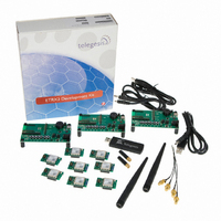
Telegesis ETRX35xDVK Development Kit ETRX35xDVK– TELEGESIS DEVELOPMENT KIT FOR ZIGBEE® ©2010 Telegesis (UK) Ltd TECHNOLOGY PRODUCT MANUAL ETRX35xDVK Product Manual (Rev 1.01) TG-ETRX35xDVK-PM-012-101 Product Manual 1.01 ...
Page 2
ETRX35xDVK – Development Kit Functional Summary Devkit Features • ZigBee Networking “Out-of-the-Box” • Low cost evaluation platform for ZigBee wireless mesh networking • Designed to set up a ZigBee mesh network in only a few minutes without the need ...
Page 3
ETRX35XDVK – DEVELOPMENT KIT FUNCTIONAL SUMMARY..................................... 2 2 ABSOLUTE MAXIMUM RATINGS OF THE DEVBOARD ................................................... 4 3 OPERATING CONDITIONS OF THE DEVBOARD ............................................................. 4 4 ELECTRICAL SPECIFICATIONS ........................................................................................ 4 5 INTEROPERABILITY ........................................................................................................... 4 6 OVERVIEW........................................................................................................................... 5 6.1 The Development ...
Page 4
Absolute Maximum Ratings of the Devboard Parameter Supply Voltage V DD Voltage on any I/O pin Storage Temperature range The absolute maximum ratings given above should under no circumstances be violated. Stress exceeding one or more of the limiting ...
Page 5
Overview The ETRX35xDVK development kit has been designed to allow quick evaluation and prototyping using the ETRX35x ZigBee modules. This document is intended to describe the hardware and accompanying software of the development kits. To learn more about the ...
Page 6
LEDs and a beeper, all of are connected to the I/Os of the module as described later in this document. 6.2 The carrier board The carrier board has an ETRX35x module plus two LEDs, and a connector to attach ...
Page 7
Setting up the Hardware In the development kits are all four versions of the module. They can be powered from either a USB hub, the mains (via a suitable power supply) or batteries. Figure 3. ETRX357-LR Module on Carrierboard ...
Page 8
Default direction Name Index Pad S17= 0142CC PC7 PC6 PC5 PC4 PC3 PC2 PC1 PC0 10 27 Out PB7 ...
Page 9
The Development Board 9.1 Development Board Interface Description Figure 4 shows the location of the connectors described below. Programming Connector: ETRX35x module from an Ember InSight Adaptor duplicated on the carrier board, and will not normally be ...
Page 10
I/O breakout: JP1 and JP2 give access to the I/O on the ETRX35x module. The individual pins are labelled on the circuit board, and the pin numbering (PA0, PB1 etc) matches that of the EM35x chip inside the module. Pin ...
Page 11
Power supply jumpers: links must be inserted at JP3 and JP6 according to the DC supply feed. JP3 can be left connected at all time, but it disconnects the serial interface lines and prevents power drain through them when the ...
Page 12
The Carrier Board The ETRX35x carrier board has two LEDs. Pin PA6 PA7 Programming Connector: ETRX35x module from an Ember InSight Adaptor. Watch crystal: an optional 32kHz crystal and its associated capacitors can be fitted at X3, C1 and ...
Page 13
The installer will first ask you to confirm the location for the files: After the files are installed you may have to restart the computer: After you connect the devboard Windows® will prompt that new hardware has been found. If ...
Page 14
Telegesis (UK) Ltd Figure 12. Found New Hardware Wizard Figure 13. Install software Automatically - 14 - ETRX35xDVK Product Manual (Rev 1.01) ETRX35x Development Kit ...
Page 15
Please note that each devboard and USB stick has a unique serial number which requires the installation procedure to be repeated with every new unit being attached to the computer. This allows multiple devices to be used on the same ...
Page 16
Once the correct COM port has been selected, the Telegesis Terminal software can be used to control the devboard as described in chapter 10. ©2010 Telegesis (UK) Ltd Figure 15. Device Manager Figure 16. Telegesis Terminal - 16 - ETRX35xDVK ...
Page 17
Application Software The command line of the ETRX35x can be accessed using any terminal software program such as HyperTerminal®. Simply set up HyperTerminal® to connect to the appropriate COM port at 19200bps, Data bits - 8, Parity - none, ...
Page 18
Software Set-up Before installing Telegesis Terminal, you must install .NET Framework Version 1.1 Redistributable Package from Microsoft. This is currently available at www.microsoft.com/downloads/browse.aspx?displaylang=en&productID=C9C8FCFB-BFF3-40CA- B59D-216F6850000A. Note that Version 2 or later is not sufficient as it supplements Version 1.1 but ...
Page 19
The application software also allows you to add custom command buttons and edit existing command buttons. New groups of commands can be created and command buttons can be moved between groups. To learn more about how to do this please ...
Page 20
Network Setup Figure 20. Command Line Interactions Once the network is established, remote nodes can be powered up ready to join in. If you have serial access to remote nodes simply issue the AT+JN command or press the ‘Join ...
Page 21
Configuring Buttons for your Setup You can easily discover the basic principles of mesh networking. Simply move a Development Board out of range (if you do not have enough space simply turn the transmit power down or put it ...
Page 22
Temperature display Telegesis Terminal includes a demonstration of how data can be collected from remote nodes and displayed on a central “sink” node. To activate the graph function: 1. Define the module on the data-gathering development board as the ...
Page 23
Firmware upgrades If required, the firmware of the ETRX35x modules can be upgraded serially as well as over the air. (Note: at the time of writing over-the-air upgrading is not yet available.) 12.1 Firmware Upgrades via Serial Port In ...
Page 24
Pressing ‘1’ initiates the upload of the new firmware and a number of ‘C’ characters will indicate that the ETRX35x is ready to receive data. Within 60 seconds, select Tools / Transfer File… and browse for the new firmware file. ...
Page 25
Over the Air Firmware Upgrades Upgrading over the air is possible by cloning a local node’s firmware to a remote node new firmware has to be introduced to the network it can be downloaded serially to a ...
Page 26
Devboard Schematic ©2010 Telegesis (UK) Ltd ETRX35x Development Kit - 26 - ETRX35xDVK Product Manual (Rev 1.01) ...
Page 27
Telegesis (UK) Ltd ©2010 Telegesis (UK) Ltd ETRX35x Development Kit ETRX35x Development Kit - ETRX35xDVK Product Manual (Rev 1.01) ETRX35xDVK Product Manual (Rev 1.01) ...
Page 28
Carrier Board Schematic ©2010 Telegesis (UK) Ltd ETRX35x Development Kit - 28 - ETRX35xDVK Product Manual (Rev 1.01) ...
Page 29
ETRX35x Ordering Information Ordering/Product Code ETRX35x ETRX35xHR ETRX35xDVK Notes: • Customers’ PO’s must state the Ordering/Product Code. • There is no “blank” version of the ETRX35x Module available. All Modules carry the Telegesis AT style Command Layer based on ...
Page 30
Trademarks All trademarks, registered trademarks and products names are the sole property of their respective owners. 17 Disclaimer Product and Company names and logos referenced may either be trademarks or registered trademarks of their respective companies. All information is ...