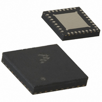
MC13202FCR2 Freescale Semiconductor, MC13202FCR2 Datasheet - Page 6

MC13202FCR2
Manufacturer Part Number
MC13202FCR2
Description
IC TXRX RF 2.4GHZ 32-QFN
Manufacturer
Freescale Semiconductor
Datasheet
1.MC13202FCR2.pdf
(30 pages)
Specifications of MC13202FCR2
Frequency
2.4GHz
Data Rate - Maximum
250kbps
Modulation Or Protocol
802.15.4
Applications
AMR, HID, HVAC, ISM
Power - Output
-27dBm ~ 3dBm
Sensitivity
-92dBm
Voltage - Supply
2 V ~ 3.4 V
Current - Receiving
37mA
Current - Transmitting
30mA
Data Interface
PCB, Surface Mount
Antenna Connector
PCB, Surface Mount
Operating Temperature
-40°C ~ 85°C
Package / Case
32-QFN
Operating Temperature (min)
-40C
Operating Temperature (max)
85C
Operating Temperature Classification
Industrial
Lead Free Status / RoHS Status
Lead free / RoHS Compliant
Memory Size
-
Lead Free Status / Rohs Status
Compliant
Other names
MC13202FCR2
MC13202FCR2TR
MC13202FCR2TR
4.2
In the receive signal path, the RF input is converted to low IF In-phase and Quadrature (I & Q) signals
through two down-conversion stages. A Clear Channel Assessment (CCA) can be performed based upon
the baseband energy integrated over a specific time interval. The digital backend performs Differential
Chip Detection (DCD), the correlator “de-spreads” the Direct Sequence Spread Spectrum (DSSS) Offset
QPSK (O-QPSK) signal, determines the symbols and packets, and detects the data.
The preamble, SFD, and FLI are parsed and used to detect the payload data and FCS which are stored in
RAM. A two-byte FCS is calculated on the received data and compared to the FCS value appended to the
transmitted data, which generates a Cyclical Redundancy Check (CRC) result. Link Quality is measured
over a 64 µs period after the packet preamble and stored in RAM.
If the MC13202 is in packet mode, the data is processed as an entire packet. The MCU is notified that an
entire packet has been received via an interrupt.
If the MC13202 is in streaming mode, the MCU is notified by an interrupt on a word-by-word basis.
Figure 4
about -57 dBm input power which is well above 802.15.4 Standard requirements.
detection/LQI reported level versus input power.
6
shows CCA reported power level versus input power. Note that CCA reported power saturates at
Receive Path Description
For both graphs, the required 802.15.4 Standard accuracy and range limits
are shown. A 3.5 dBm offset has been programmed into the CCA reporting
level to center the level over temperature in the graphs.
Figure 4. Reported Power Level versus Input Power in CCA Mode
-100
-50
-60
-70
-80
-90
-90
MC13202 Technical Data, Rev. 1.5
-80
NOTE
Input Pow er (dBm)
-70
802.15.4 Ac curac y
and range Requirements
-60
-50
Figure 5
Freescale Semiconductor
shows energy


