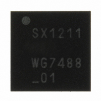
SX1211I084TRT Semtech, SX1211I084TRT Datasheet - Page 25

SX1211I084TRT
Manufacturer Part Number
SX1211I084TRT
Description
IC SNGL-CHIP TXRX 32-TQFN
Manufacturer
Semtech
Specifications of SX1211I084TRT
Frequency
860 ~ 960MHz
Data Rate - Maximum
200kbps
Modulation Or Protocol
FSK, OOK
Applications
AMR, ISM, Security and Access
Power - Output
12.5dBm
Sensitivity
-113dBm
Voltage - Supply
2.1 V ~ 3.6 V
Current - Receiving
3mA
Current - Transmitting
25mA
Data Interface
PCB, Surface Mount
Antenna Connector
PCB, Surface Mount
Operating Temperature
-40°C ~ 85°C
Package / Case
32-TQFN
Operating Temperature (min)
-40C
Operating Temperature (max)
85C
Operating Temperature Classification
Industrial
Modulation Type
FSK/OOK
Package Type
TQFN EP
Operating Supply Voltage (min)
2.1V
Operating Supply Voltage (typ)
2.5/3.3V
Operating Supply Voltage (max)
3.6V
Lead Free Status / RoHS Status
Lead free / RoHS Compliant
Memory Size
-
Lead Free Status / Rohs Status
Compliant
Other names
SX1211I084TRT
Available stocks
Company
Part Number
Manufacturer
Quantity
Price
Company:
Part Number:
SX1211I084TRT
Manufacturer:
HITTITE
Quantity:
560
As can be seen from Figure 17, the required bandwidth of this filter varies between the two demodulation modes.
The bits RXParam_ButterFilt set fc, the cutoff frequency of the filter. As we are in a Zero-IF configuration, the FSK
lobes are centered around the virtual “DC” frequency. The choice of fc should be such that the modulated signal
falls in the filter bandwidth, anticipating the Local Oscillator frequency drift over the operating temperature and
aging of the device:
Please refer to the charts in section 3.4.5 for an accurate overview of the filter bandwidth vs. setting.
The bits RXParam_PolypFilt_center set fo, the center frequency of the polyphase filter when activated. fo should
always be chosen to be equal to the low Intermediate Frequency of the receiver (IF2). This is why, in the GUI
described in section 7.2.1 of this document, the low IF frequency of the OOK receiver denoted IF2 has been
replaced by fo.
The following setting is recommended:
The value stored in RXParam_ButterFilt determines fc, the filter cut-off frequency. So the user should set fc
according to:
Again, fc as a function of RXParam_ButterFilt is given in the section 3.4.6.
Fc, the 3dB cutoff frequency of the Butterworth filter used in FSK reception, is programmed through the bit
RXParam_ButterFilt. However, the whole receiver chain influences this cutoff frequency. Thus the channel select
and resultant filter bandwidths are summarized in the following chart:
Rev 7 – Sept 2
ADVANCED COMMUNICATIONS & SENSING
FSK mode: The 99% energy bandwidth of an FSK modulated signal is approximated to be:
OOK mode: The 99% energy bandwidth of an OOK modulated signal is approximated to be:
3.4.5. Channel Filters Setting in FSK Mode
nd
, 2008
2
BW
2
RXParam
fo
( *
*
BW
99
fc
fc
100
%,
99
FSK
%,
fo
kHz
OOK
BW
)
Page 25 of 92
_
PolypFilt
2
99
BW
*
%,
Tbit
99
FSK
2
Fdev
%,
OOK
LO
. 2
"
LO
0011
BR
BR
2
drifts
drifts
"
www.semtech.com
SX1211


