20-101-1221 Rabbit Semiconductor, 20-101-1221 Datasheet - Page 72
20-101-1221
Manufacturer Part Number
20-101-1221
Description
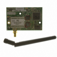
RCM4400W (JAPAN TELEC CERTIFIED)
Manufacturer
Rabbit Semiconductor
Series
RabbitCore®r
Datasheet
1.20-101-1202.pdf
(126 pages)
Specifications of 20-101-1221
Frequency
2.4GHz
Modulation Or Protocol
802.11 b
Power - Output
16dBm
Voltage - Supply
3.3V
Current - Receiving
450mA
Current - Transmitting
450mA
Data Interface
Connector, 2 x 25 Header
Memory Size
512K Flash, 1MB SRAM
Antenna Connector
SMA
Operating Temperature
-20°C ~ 85°C
Package / Case
Module
Lead Free Status / RoHS Status
Lead free / RoHS Compliant
Applications
-
Sensitivity
-
Data Rate - Maximum
-
Other names
316-1147


•
•
66
The next macro specifies a suitable pre-shared key. The key may be entered either as 64
hexadecimal digits or as an ASCII string of up to 63 characters.
When you assign your own key, there is a good chance of typos since the key is long. It
is advisable to enter the key in this macro first, then copy and paste into your access
point to ensures that both the RCM4400W and the access point have the same key.
Initially, it may be easier to use the 64 hexadecimal digits form of the key rather than
the ASCII passphrase. A passphrase requires considerable computation effort, which
delays the startup of the sample by about 40 seconds.
If you want to add authentication, set the authentication to “open system,” which basi-
cally means that knowing the key is sufficient to allow access.
Change
change the amount of time in milliseconds between the outgoing pings.
Uncomment the
Once you have compiled the sample program and it is running, LED DS2 will flash
when a ping is sent, and LED DS3 will flash when a ping is received.
POWERDOWN.C
Wi-Fi circuit to reduce power consumption. Note that powering down the Wi-Fi portion
of the RCM4400W module results in a loss of the network interface (unlike an Ethernet
connection), and so is only suitable for applications such as data logging where only
intermittent network connectivity is required.
The sample program demonstrates the powerdown operation as a simple sequential
state machine. LED DS2 on the Prototyping Board will be on when the network inter-
face is up, and LED DS3 will be on when the Wi-Fi circuit is powered up.
Before you compile and run this sample program, modify the configuration macros,
including the
down for these intervals.
SMTP.C
the S2 and S3 switches on the Prototyping Board are pressed. LEDs DS2 and DS3 on
the Prototyping Board will light up when e-mail is being sent.
#define _WIFI_PSK_HEX
#define WIFI_AUTH WIFICONF_AUTH_OPEN_SYS
PING_WHO
—This program demonstrates using the SMTP library to send an e-mail when
DOWNTIME
—This program demonstrates how to power down the FPGA chip in the
VERBOSE
to the host you want to ping. You may modify
and the
define to see the incoming ping replies.
UPTIME
values. The interface will be powered up and
RabbitCore RCM4400W
PING_DELAY
to
Related parts for 20-101-1221
Image
Part Number
Description
Manufacturer
Datasheet
Request
R

Part Number:
Description:
COMPUTER SGL-BRD BL2500 29.4MHZ
Manufacturer:
Rabbit Semiconductor
Datasheet:

Part Number:
Description:
COMPUTER SGL-BRD BL2500 29.4MHZ
Manufacturer:
Rabbit Semiconductor
Datasheet:

Part Number:
Description:
DISPLAY GRAPHIC 12KEY PROG OP670
Manufacturer:
Rabbit Semiconductor
Datasheet:
Part Number:
Description:
DISPLAY GRAPHIC 12KEY ETH OP6700
Manufacturer:
Rabbit Semiconductor
Datasheet:

Part Number:
Description:
COMPUTER SINGLE-BOARD BL2030
Manufacturer:
Rabbit Semiconductor
Part Number:
Description:
COMPUTER SGL-BOARD ETH BL2010
Manufacturer:
Rabbit Semiconductor

Part Number:
Description:
MODULE OP6810 W/O ETH/MEM EXPANS
Manufacturer:
Rabbit Semiconductor
Datasheet:
Part Number:
Description:
COMPUTER SINGLE-BOARD BL2020
Manufacturer:
Rabbit Semiconductor
Part Number:
Description:
COMPUTER BL2010 W/FRICTION LOCK
Manufacturer:
Rabbit Semiconductor
Part Number:
Description:
COMPUTER BL2020 W/FRICTION LOCK
Manufacturer:
Rabbit Semiconductor
Part Number:
Description:
COMPUTER SGL-BRD BL2500 44.2MHZ
Manufacturer:
Rabbit Semiconductor
Datasheet:
Part Number:
Description:
COMPUTER SGL-BOARD FULL BL2000
Manufacturer:
Rabbit Semiconductor

Part Number:
Description:
COMPUTER SINGLE-BOARD BL2110
Manufacturer:
Rabbit Semiconductor

Part Number:
Description:
COMPUTER SGL-BRD 29.4MHZ BL2610
Manufacturer:
Rabbit Semiconductor
Datasheet:
Part Number:
Description:
INTERFACE OP6800 512K FLASH&SRAM
Manufacturer:
Rabbit Semiconductor
Datasheet: