20-101-1221 Rabbit Semiconductor, 20-101-1221 Datasheet - Page 30
20-101-1221
Manufacturer Part Number
20-101-1221
Description
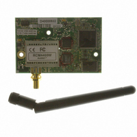
RCM4400W (JAPAN TELEC CERTIFIED)
Manufacturer
Rabbit Semiconductor
Series
RabbitCore®r
Datasheet
1.20-101-1202.pdf
(126 pages)
Specifications of 20-101-1221
Frequency
2.4GHz
Modulation Or Protocol
802.11 b
Power - Output
16dBm
Voltage - Supply
3.3V
Current - Receiving
450mA
Current - Transmitting
450mA
Data Interface
Connector, 2 x 25 Header
Memory Size
512K Flash, 1MB SRAM
Antenna Connector
SMA
Operating Temperature
-20°C ~ 85°C
Package / Case
Module
Lead Free Status / RoHS Status
Lead free / RoHS Compliant
Applications
-
Sensitivity
-
Data Rate - Maximum
-
Other names
316-1147


•
24
IOCONFIG_SWITCHECHO.C
and F, which then transmit and then receive an ASCII string when switch S2 or S3 is
pressed. The echoed serial data are displayed in the Dynamic C
Note that the I/O lines that carry the Serial Port E and F signals are not the Rabbit 4000
defaults. The Serial Port E and F I/O lines are configured by calling the library function
serEFconfig()
found in the Dynamic C
Note that the
support this sample program is provided in the Dynamic C
SERIAL
Serial Port E is configured to use Parallel Port D bits PD6 and PD7. These signals are
available on the Prototyping Board's Module Extension Header (header J2).
Serial Port F is configured to use Parallel Port C bits PC2 and PC3. These signals are
available on the Prototyping Board's RS-232 connector (header J4).
Serial Port D is left in its default configuration, using Parallel Port C bits PC0 and PC1.
These signals are available on the Prototyping Board's RS-232 connector (header J4).
Serial Port D transmits and then receives an ASCII string with Serial Port F when
switch S3 is pressed.
To set up the Prototyping Board, you will need to tie TxC
and RxD together on the RS-232 header at J4 using the
jumpers supplied in the Development Kit; you will also
tie TxE (PD6) and RxE (PD7) together with a soldered
wire or with a wire jumper if you have soldered in the
IDC header supplied with the accessory parts in the
Development Kit.
Once you have compiled and run this program, press and
release switches S2 or S3 on the Prototyping Board. The data echoed between the serial
ports will be displayed in the
folder.
RCM4400W_IOCONFIG.LIB
that was generated by the Rabbit 4000
Utilities
—This program demonstrates how to set up Serial Ports E
STDIO
folder.
window.
library generated by
IOCONFIG.EXE
SAMPLES\RCM4400W\
IOCONFIG.EXE
STDIO
RabbitCore RCM4400W
window.
utility program
to
Related parts for 20-101-1221
Image
Part Number
Description
Manufacturer
Datasheet
Request
R

Part Number:
Description:
COMPUTER SGL-BRD BL2500 29.4MHZ
Manufacturer:
Rabbit Semiconductor
Datasheet:

Part Number:
Description:
COMPUTER SGL-BRD BL2500 29.4MHZ
Manufacturer:
Rabbit Semiconductor
Datasheet:

Part Number:
Description:
DISPLAY GRAPHIC 12KEY PROG OP670
Manufacturer:
Rabbit Semiconductor
Datasheet:
Part Number:
Description:
DISPLAY GRAPHIC 12KEY ETH OP6700
Manufacturer:
Rabbit Semiconductor
Datasheet:

Part Number:
Description:
COMPUTER SINGLE-BOARD BL2030
Manufacturer:
Rabbit Semiconductor
Part Number:
Description:
COMPUTER SGL-BOARD ETH BL2010
Manufacturer:
Rabbit Semiconductor

Part Number:
Description:
MODULE OP6810 W/O ETH/MEM EXPANS
Manufacturer:
Rabbit Semiconductor
Datasheet:
Part Number:
Description:
COMPUTER SINGLE-BOARD BL2020
Manufacturer:
Rabbit Semiconductor
Part Number:
Description:
COMPUTER BL2010 W/FRICTION LOCK
Manufacturer:
Rabbit Semiconductor
Part Number:
Description:
COMPUTER BL2020 W/FRICTION LOCK
Manufacturer:
Rabbit Semiconductor
Part Number:
Description:
COMPUTER SGL-BRD BL2500 44.2MHZ
Manufacturer:
Rabbit Semiconductor
Datasheet:
Part Number:
Description:
COMPUTER SGL-BOARD FULL BL2000
Manufacturer:
Rabbit Semiconductor

Part Number:
Description:
COMPUTER SINGLE-BOARD BL2110
Manufacturer:
Rabbit Semiconductor

Part Number:
Description:
COMPUTER SGL-BRD 29.4MHZ BL2610
Manufacturer:
Rabbit Semiconductor
Datasheet:
Part Number:
Description:
INTERFACE OP6800 512K FLASH&SRAM
Manufacturer:
Rabbit Semiconductor
Datasheet: