WISMC03BI Laird Technologies, WISMC03BI Datasheet - Page 16
WISMC03BI
Manufacturer Part Number
WISMC03BI
Description
MODULE LAN 802.11B/G BISM
Manufacturer
Laird Technologies
Series
EZURiOr
Specifications of WISMC03BI
Frequency
2.4GHz
Data Rate - Maximum
1Mbps
Modulation Or Protocol
802.11 b/g
Applications
AMR, Automotive, ISM
Power - Output
15dBm
Sensitivity
-86dBm
Voltage - Supply
3.3 V ~ 5.5 V
Current - Transmitting
250mA
Data Interface
Connector, 50 Pin, DF-12
Memory Size
64Mbyte Flash, 16MByte SRAM
Antenna Connector
U.FL
Operating Temperature
-40°C ~ 85°C
Package / Case
Module
Wireless Frequency
2.412 GHz to 2.484 GHz
Interface Type
UART
Board Size
22.8 mm x 33.8 mm x 7.6 mm
Modulation
BPSK, CCK, DSSS, QPSK
Security
WEP 64/128, WPA-PSK, WPA2, TKIP, AES-CCMP
Lead Free Status / RoHS Status
Lead free / RoHS Compliant
Current - Receiving
-
Lead Free Status / Rohs Status
Lead free / RoHS Compliant


8.6
The WISM connects to a motherboard by means of a board-to-board connector that is supplied by
Hirose. Mating headers from Hirose are available in different stacking heights, allowing the spacing
between the WISM module and carrier pcb to be changed from 3.5mm to 5.0mm.
Notes: The headers listed above are with boss and metal fitting.
8.7
See
8.8
There are many ways to properly install the Module in the host device. An efficient approach is to
mount the PCB to a frame, plate, rack or chassis. Fasteners can be M1.8 or M2 screws plus suitable
washers, circuit board spacers, or customized screws, clamps, or brackets in 2.2mm diameter holes.
Note that care should be taken to ensure the head of the fixing does not interfere with the circuit.
Nylon fixings are recommended.
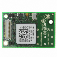
The antenna (brown square component on top side of PCB) must not be influenced by any other PCBs,
components or by the housing of the host device. The proximity of the antenna to large metallic objects
can affect the range and performance of the system. Designers should carefully consider the location of
the Module and the type of enclosure material that is used.
To prevent mechanical damage, be careful not to force, bend or twist the Module. Be sure it is
positioned flat against the host device.
DSH_WISMC03_0v97 WISM 40 pin SLIP Data Sheet.doc
Item
Receptacle on Module
Headers DF12 series
Parameter
Number of Contacts
Quantity delivered
Voltage
Current Rating
Resistance
Dielectric Withstanding Voltage
Operating Temperature
Contact Material
Insulator
Stacking height
Insertion force
Withdrawal force 1st to 50th
Maximum connection cycles
http://www.hirose.co.jp/cataloge_hp/e53700036.pdf
Board to board connector and stacking height
Suffix -86 denotes RoHS compliance.
Hirose Connector general specification
Mounting the Module onto the application platform
Part number
DF12C-40DS-0.5V(86)
DF12(3.5)-40DP-0.5V(86)
DF12(4.0)-40DP-0.5V(86)
DF12(5.0)-40DP-0.5V(86)
Specification (40 pin Board to Board connector)
40
2000 Connectors per Tape & Reel
50V
0.5A max per contact
0.05 Ohm per contact
500V RMS min
phosphor bronze (surface: gold plated)
Material PA , beige natural
3.0 mm ; 3.5 mm ; 4.0 mm ; 5.0 mm
21.8N
10N
50
-45°C to +125°C
© 2007-8 EZURiO Ltd
for detail information on the PCB socket.
Stacking height
3.5 mm – 5 mm
3.5 mm
4.0 mm
5.0 mm
HRS number
CL537-0007-7-86
CL537-0032-4-86
CL537-0057-5-86
CL537-0157-0-86
Page 16
Related parts for WISMC03BI
Image
Part Number
Description
Manufacturer
Datasheet
Request
R

Part Number:
Description:
Bluetooth Serial Module Development Kit
Manufacturer:
Laird Technologies
Part Number:
Description:
BLUETOOTH MODULE DEVELOPMENT KIT
Manufacturer:
Laird Technologies
Part Number:
Description:
Bluetooth 2.0 AT Data Module, Internal Antenna Development Kit
Manufacturer:
Laird Technologies

Part Number:
Description:
BLUETOOTH EVAL BOARD BTM511
Manufacturer:
Laird Technologies
Datasheet:

Part Number:
Description:
Bluetooth / 802.15.1 Modules & Development Tools BLUETTH Multimed MODLE, No ANT DEVKIT
Manufacturer:
Laird Technologies
Datasheet:

Part Number:
Description:
DEV KIT PRM122
Manufacturer:
Laird Technologies
Datasheet:
Part Number:
Description:
DEV KIT PRM123
Manufacturer:
Laird Technologies
Datasheet:

Part Number:
Description:
KIT FOR PRM112
Manufacturer:
Laird Technologies
Datasheet:
Part Number:
Description:
DEV KIT PRM121
Manufacturer:
Laird Technologies
Datasheet:

Part Number:
Description:
KIT DEVELOPMENT FOR LT2510 U.FL
Manufacturer:
Laird Technologies
Datasheet:

Part Number:
Description:
CHOKE COMMON MODE 110 OHMS SMD
Manufacturer:
Laird Technologies
Datasheet: