WISMC03BI Laird Technologies, WISMC03BI Datasheet
WISMC03BI
Specifications of WISMC03BI


Related parts for WISMC03BI


WISMC03BI Summary of contents
Page 1
... WISMC03BI WIRELESS LAN MODULE / DEVICE SERVER USER MANUAL Innovative Technology for a Connected World ...
Page 2
... WISMC03BI Wireless LAN Module / Device Server REVISION REVISION HISTORY HISTORY Revision www.lairdtech.com 2 Description Laird Technologies ...
Page 3
... WISMC03BI Wireless LAN Module / Device Server TABLE OF CONTENTS CONTENTS WISMC03BI Wireless LAN Module / Device Server ... 4 Overview ..........................................................................4 WISMC03BI Key Features ................................................4 Specifications ............................................................... 5 Detailed Specifications .....................................................5 Block Diagram ..................................................................7 Mechanical Specifications .......................................... 8 Wireless LAN Module Dimensional Outline .....................8 Electrical Specifications .............................................. 9 40 Way Hirose Pin Descriptions .......................................9 Absolute Maximum Ratings ...........................................10 Recommended Operating Parameters ...
Page 4
... WISMC03BI Wireless LAN Module / Device Server OVERVIEW AND Laird Technologies’ 802.11b/g SLIP Wireless LAN Module is a fully integrated and qualified wireless device KEY FEATURES server sub-system, designed to make it simple to embed 802.11 connectivity. It has been designed to be pin compatible with the footprint of Siemens MC55 GPRS modules, allowing designers to design one pcb to support either GPRS or Wireless LAN connectivity ...
Page 5
... WISMC03BI Wireless LAN Module / Device Server SPECIFICATIONS CATEGORIES Wireless Specification Antenna Modes UART Interface General Purpose Interface †DSR, DTR, RI and DCD are configurable either as GPIO or as modem control lines. www.lairdtech.com 5 FEATURE IMPLEMENTATION Standards Supported IEEE 802.11b, IEEE 802.11g Frequency 2.412 – 2.484 GHz Channels 11 channels – ...
Page 6
... WISMC03BI Wireless LAN Module / Device Server SPECIFICATIONS CATEGORIES Security Protocols Power Consumption Supply Voltage Embedded Wireless Processor System Coexistence / Compatibility Connections Physical Environmental Approvals Miscellaneous www.lairdtech.com 6 FEATURE IMPLEMENTATION Open Connection WEP encryption 64 and 128 bit options WPA-PSK WPA2 Enterprise & Personal IEEE 802 ...
Page 7
... WISMC03BI Wireless LAN Module / Device Server SPECIFICATIONS BLOCK DIAgRAM The module has a 40 way Hirose connector which provides a compatible pin out to the same form factor Laird Technologies Bluetooth Intelligent Serial Module. www.lairdtech.com 7 Laird Technologies ...
Page 8
... WISMC03BI Wireless LAN Module / Device Server MECHANICAL WIRELESS LAN MODULE DIMENSIONAL OUTLINE SPECIFICATIONS All dimensions in mm NOTES 1. RF antenna 2. External Antenna connector (Hirose U.FL-R-SMT) 3. Board to board connector (Hirose connector) 4. 2.0mm maximum top side component height (excluding antenna) 5. 1.5mm maximum bottom side component height 6 ...
Page 9
... WISMC03BI Wireless LAN Module / Device Server ELECTRICAL 40 WAY HIROSE PIN DESCRIPTIONS SPECIFICATIONS The Hirose DF12C board-to-board connector on the module is a 40-pin double-row receptacle. The table below defines the pin functions. The pin-out is as viewed from the underside of the Module. PIN Notes: The reset circuitry within the module incorporates a brown-out detector ...
Page 10
... WISMC03BI Wireless LAN Module / Device Server ELECTRICAL ABSOLUTE MAxIMUM RATINgS SPECIFICATIONS Absolute maximum ratings for supply voltage and voltages on digital and analogue pins of the Module are listed below. Exceeding these values will cause permanent damage. PARAMETER Peak current of power supply Voltage at digital pins ...
Page 11
... WISMC03BI Wireless LAN Module / Device Server ELECTRICAL Signal Levels for Bluetooth Coexistence and Wakeup Pins SPECIFICATIONS SIGNAL TYPE Input Output Bluetooth Coexistence SIGNAL NAME WLAN_ACTIVE BT_PRIORITY BT_STATE Wakeup SIGNAL NAME WAKEUP 11 www.lairdtech.com SIGNAL LEVEL V max=1. min=1. max=3. max=0. min=2.4V OH PIN NO I/O ...
Page 12
... WISMC03BI Wireless LAN Module / Device Server RF PERFORMANCE TRANSMIT POWER (802.11g) SPECIFICATIONS Conducted Transmit Power Antenna Gain (Integrated Antenna) Effective Transmit Power TRANSMIT POWER (802.11B) Conducted Transmit Power Antenna Gain (Integrated Antenna) Effective Transmit Power RECEIVE SENSITIVITY (802.11B) Receive Sensitivity (11Mbps) Antenna Gain (Integrated Antenna) Effective Receive Sensitivity RECEIVE SENSITIVITY (802 ...
Page 13
... WISMC03BI Wireless LAN Module / Device Server FUNCTIONAL The Wireless LAN module is designed for use with a host system that implements a TCP/IP stack. It provides a DESCRIPTION UDP stack and SLIP interface to allow fast integration. The integrated, high performance antenna together with the RF and baseband circuitry provides the Wireless LAN connectivity and the UART interface for a connection to a host system ...
Page 14
... WISMC03BI Wireless LAN Module / Device Server FUNCTIONAL Bluetooth Coexistence DESCRIPTION Three pins are provided to allow implementation of Bluetooth coexistence schemes, when the 802.11 module is collocated with a Bluetooth radio. These connect directly between the basebands of the two radios to ensure minimum interference. Both 2-wire and 3-wire coexistence schemes can be supported. ...
Page 15
... WISMC03BI Wireless LAN Module / Device Server FIRMWARE COMMAND SET FEATURES The module supports the following commands. Details of the complete command list are provided in a separate Programming Guide, the following are a provided as an overview. COMMAND UARTMODIFY SECURITY KEY AUTHENTICATE SEARCH ATTACH DETACH ...
Page 16
... WISMC03BI Wireless LAN Module / Device Server FIRMWARE POWER SAVINg FEATURES The module supports the Wireless LAN IEEE power saving function. When this power saving mode is enabled, the wireless LAN chipset goes to sleep when it is not actively receiving from the access point. The chipset wakes regular basis to receive broadcast messages from the transmit or receive unicast messages ...
Page 17
... WISMC03BI Wireless LAN Module / Device Server APPLICATION ANTENNA LOCATION INFORMATION The antenna used on the Wireless LAN module is designed to be largely immune from the effects of proximity detuning. Normally, antennas operating at 2.4GHz are affected by their surroundings, so that great care is needed in their placement and orientation. ...
Page 18
... WISMC03BI Wireless LAN Module / Device Server APPLICATION ExTERNAL ANTENNA INFORMATION The approval of the module was performed using a 3dBi external antenna from RF Castle Electronics (www.rfcastle.com/pdf/RF-3dbi%20DipoleA.pdf). The antenna was connected using a short cable to convert from the U.FL connector on the module to a reverse SMA. The conditions of approval allow the use of an alternative antenna, but require that the resulting effective radiated power does not exceed that exhibited during the approvals testing ...
Page 19
... WISMC03BI Wireless LAN Module / Device Server APPLICATION BOARD TO BOARD CONNECTOR AND STACKINg HEIgHT INFORMATION The WISM connects to a motherboard by means of a board-to-board connector that is supplied by Hirose. Mating headers from Hirose are available in different stacking heights, allowing the spacing between the WISM module and carrier pcb to be changed from 3.5mm to 5.0mm. ...
Page 20
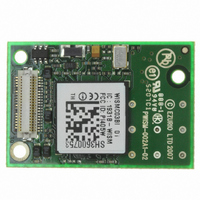
... The label contains the part number, firmware version loaded at manufacture, serial number, and statutory approvals information. ORDERINg INFORMATION The WISM described in this data sheet should be ordered using the part number below: PART NUMBER WISMC03BI 20 www.lairdtech.com PART NUMBER SOURCE NPR2005-153-3.6 Laird Technologies / Richco NPR2005-153-4 ...
Page 21
... WISMC03BI Wireless LAN Module / Device Server QUALIFICATION QUALIFICATION PROCESS The following safety precautions must be observed during all phases of the operation, usage, service or repair of any application incorporating this Module. Manufacturers of the RF equipment are advised to convey the following safety information to users and operating personnel and to incorporate these guidelines into all manuals supplied with the product ...
Page 22
... WISMC03BI Wireless LAN Module / Device Server RELATED RELATED DOCUMENTS DOCUMENTS AN008 - Wireless Development Kit User Guide AN016 - Notification Requirements for Wireless Products. AN017 – Interfacing to the WISM ADC input WHP-050004-1V0 Bluetooth and 802.11 Coexistence WISM SLIP Programming Manual Documents are available for download from www.lairdtech.com ...
Page 23
... WISMC03BI Wireless LAN Module / Device Server DISCLAIMERS LAIRD TECHNOLOGIES’ WIRELESS PRODUCTS ARE NOT AUTHORISED FOR USE AS CRITICAL COMPONENTS IN LIFE SUPPORT DEVICES OR SYSTEMS WITHOUT THE EXPRESS WRITTEN APPROVAL OF THE MANAGING DIRECTOR OF LAIRD TECHNOLOGIES. The definitions used herein are: a) Life support devices or systems are devices which (1) are intended for surgical implant into the body, or (2) support or sustain life and whose failure to perform when properly used in accordance with the instructions for use provided in the labelling can reasonably be expected to result in a significant injury to the user ...
Page 24
... LWS-UM-WISMC03BI 0409 Copyright © 2009 Laid Technologies, Inc. All rights reserved. The information contained in this manual and the accompanying software programs are copyrighted and all rights are reserved by Laird Technologies, Inc. Laird Technologies, Inc. reserves the right to make periodic modifications of this product without obligation to notify any person or entity of such revision ...