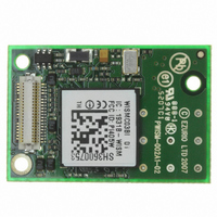
WISMC03BI Laird Technologies, WISMC03BI Datasheet - Page 15

WISMC03BI
Manufacturer Part Number
WISMC03BI
Description
MODULE LAN 802.11B/G BISM
Manufacturer
Laird Technologies
Series
EZURiOr
Specifications of WISMC03BI
Frequency
2.4GHz
Data Rate - Maximum
1Mbps
Modulation Or Protocol
802.11 b/g
Applications
AMR, Automotive, ISM
Power - Output
15dBm
Sensitivity
-86dBm
Voltage - Supply
3.3 V ~ 5.5 V
Current - Transmitting
250mA
Data Interface
Connector, 50 Pin, DF-12
Memory Size
64Mbyte Flash, 16MByte SRAM
Antenna Connector
U.FL
Operating Temperature
-40°C ~ 85°C
Package / Case
Module
Wireless Frequency
2.412 GHz to 2.484 GHz
Interface Type
UART
Board Size
22.8 mm x 33.8 mm x 7.6 mm
Modulation
BPSK, CCK, DSSS, QPSK
Security
WEP 64/128, WPA-PSK, WPA2, TKIP, AES-CCMP
Lead Free Status / RoHS Status
Lead free / RoHS Compliant
Current - Receiving
-
Lead Free Status / Rohs Status
Lead free / RoHS Compliant
The antenna finish may tarnish as a result of environmental conditions and handling. This is a cosmetic
effect and does not affect the RF performance.
8.2
The approval of the module was performed using a 3dBi external antenna from RF Castle Electronics
(www.rfcastle.com/pdf/RF-3dbi%20DipoleA.pdf).
convert from the U.FL connector on the module to a reverse SMA. The conditions of approval allow the
use of an alternative antenna, but require that the resulting effective radiated power does not exceed
that exhibited during the approvals testing.
To ensure that the approval is not affected, the TOTAL GAIN of the external antenna, including
insertion loss of the connectors and cable must be less than 3dBi. If a higher gain is employed, then
the pre-approved status of the module will be lost. Customers must also ensure that the frequency
characteristic of their antenna matches that of the antenna used for approval. As antennae are tuned
for their frequency band the use of a different antenna technology may result in a change in emissions
outside the 2.4GHz band. It is the customer’s responsibility to ensure that an external antenna does
not negate the approval.
U.FL connectors are supplied from a number of connector manufacturers. Details of Hirose’s mating
U.FL connectors are available at http://www.hirose.co.jp/cataloge_hp/e32119372.pdf
8.3
The power supply for the Module must be a single voltage source within the range of 3.3 V to 5.0 V. It
must be able to provide sufficient current for a transmit burst. This can rise to 550mA.
The Module includes on-board regulators to provide local 3.0V. This rail is accessible on pin 27 for
monitoring purposes only. Under no circumstances should this pin be used to source current.
Power (VCC_5V) is provided via the board-to-board connector Pins 28, 29 and 31. All VCC_5V and GND
pins should be connected to ensure that individual pin current capacities are not exceeded during
transmit current peaks.
8.4
The Module is provided with an active high reset pin (Hirose 40way DF12C connector pin 13).
However, on the application of power, the Power On Reset circuit built into the Module will ensure that
the unit starts correctly. The external reset signal allows the module to be reset under software control
from the host. After a power on or reset operation, the module will de-assert the UART_RTS output and
re-assert it when it is ready to receive commands.
8.5
The Wireless LAN module is designed to meet an operational temperature of -40°C to +85°C in normal
operation where it is running in IEEE power save mode.
If the module is run in a mode that results in more frequent receive and transmit activity the operating
temperature will need to be derated to ensure that overall module power dissipation limits are not
exceeded. When the ambient temperature rises above 60°C the module should only be operated in
powersave mode 1 or higher.
The Wireless LAN module can operate in temperatures as low as -40°C, but the cold start minimum
temperature must not be below -25°C.
DSH_WISMC03_0v97 WISM 40 pin SLIP Data Sheet.doc
External Antenna
Power Supply Considerations
Power-On-Reset
Operational Temperature
The antenna was connected using a short cable to
© 2007-8 EZURiO Ltd
Page 15


