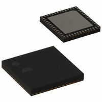
EM250-RTR Ember, EM250-RTR Datasheet - Page 54

EM250-RTR
Manufacturer Part Number
EM250-RTR
Description
IC ZIGBEE SYSTEM-ON-CHIP 48-QFN
Manufacturer
Ember
Series
EM250r
Datasheet
1.EM250-JMP-R.pdf
(117 pages)
Specifications of EM250-RTR
Frequency
2.4GHz
Modulation Or Protocol
802.15.4 Zigbee
Applications
Home/Building Automation, Industrial Control and Monitoring
Power - Output
3dBm
Sensitivity
-97dBm
Voltage - Supply
2 V ~ 3.6 V
Current - Receiving
35.5mA
Current - Transmitting
33mA
Data Interface
PCB, Surface Mount
Memory Size
128kB Flash, 5kB SRAM
Antenna Connector
PCB, Surface Mount
Operating Temperature
-40°C ~ 85°C
Package / Case
48-QFN
For Use With
636-1009 - PROGRAMMER USB FLASH EM250/260
Lead Free Status / RoHS Status
Lead free / RoHS Compliant
Data Rate - Maximum
-
Other names
636-1000-2
Available stocks
Company
Part Number
Manufacturer
Quantity
Price
Company:
Part Number:
EM250-RTR
Manufacturer:
TI
Quantity:
3 400
Part Number:
EM250-RTR
Manufacturer:
EMBER
Quantity:
20 000
EM250
SC1_DMASTAT [0x4496]
SC1_RXCNTA [0x4490]
54
SC1_RXFRMB
SC1_RXFRMA
SC1_RXPARB
SC1_RXPARA
SC_RXOVFB
SC_RXOVFA
SC_TXACTB
SC_TXACTA
SC_RXACTB
SC_RXACTA
SC1_RXCNTA
SC1_RXPARB
0-R
0-R
0-R
0-R
15
15
0
0
7
7
120-0082-000I
SC1_RXPARA
0-R
0-R
0-R
0-R
14
14
0
6
0
6
[9]
[8]
[7]
[6]
[5]
[4]
[3]
[2]
[1]
[0]
[12:0]
SC_RXOVFB
This bit is set when DMA receive buffer B was passed a frame error from the lower hardware
FIFO. This bit is autocleared the next time buffer B is loaded or when the receive DMA is reset.
This bit is set when DMA receive buffer A was passed a frame error from the lower hardware
FIFO. This bit is autocleared the next time buffer A is loaded or when the receive DMA is reset.
This bit is set when DMA receive buffer B was passed a parity error from the lower hardware
FIFO. This bit is autocleared the next time buffer B is loaded or when the receive DMA is reset.
This bit is set when DMA receive buffer A was passed a parity error from the lower hardware
FIFO. This bit is autocleared the next time buffer A is loaded or when the receive DMA is reset.
This bit is set when DMA receive buffer B was passed an overrun error from the lower hardware
FIFO. Neither receive buffers were capable of accepting any more bytes (unloaded), and the
FIFO filled up. Buffer B was the next buffer to load, and when it drained the FIFO, the overrun
error was passed up to the DMA and flagged with this bit. This bit is autocleared the next time
buffer B is loaded or when the receive DMA is reset.
This bit is set when DMA receive buffer A was passed an overrun error from the lower hardware
FIFO. Neither receive buffers were capable of accepting any more bytes (unloaded), and the
FIFO filled up. Buffer A was the next buffer to load, and when it drained the FIFO the overrun
error was passed up to the DMA and flagged with this bit. This bit is autocleared the next time
buffer A is loaded or when the receive DMA is reset.
This bit is set when DMA transmit buffer B is currently active.
This bit is set when DMA transmit buffer A is currently active.
This bit is set when DMA receive buffer B is currently active.
This bit is set when DMA receive buffer A is currently active.
A byte offset (from 0) which points to the location in DMA receive buffer A where the next byte
will be placed. When the buffer fills and subsequently unloads, this register wraps around and
holds the value zero (pointing back to the first location in the buffer).
0-R
0-R
0-R
0-R
13
13
0
5
0
5
SC_RXOVFA
0-R
0-R
0-R
0-R
12
12
0
4
4
SC1_RXCNTA
SC_TXACTB
0-R
0-R
0-R
0-R
11
11
0
3
3
SC1_RXCNTA
SC_TXACTA
0-R
0-R
0-R
0-R
10
10
0
2
2
SC1_RXFRMB
SC_RXACTB
0-R
0-R
0-R
0-R
9
1
9
1
SC1_RXFRMA
SC_RXACTA
0-R
0-R
0-R
0-R
8
0
8
0


