EM250-RTR Ember, EM250-RTR Datasheet - Page 50
EM250-RTR
Manufacturer Part Number
EM250-RTR
Description
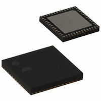
IC ZIGBEE SYSTEM-ON-CHIP 48-QFN
Manufacturer
Ember
Series
EM250r
Datasheet
1.EM250-JMP-R.pdf
(117 pages)
Specifications of EM250-RTR
Frequency
2.4GHz
Modulation Or Protocol
802.15.4 Zigbee
Applications
Home/Building Automation, Industrial Control and Monitoring
Power - Output
3dBm
Sensitivity
-97dBm
Voltage - Supply
2 V ~ 3.6 V
Current - Receiving
35.5mA
Current - Transmitting
33mA
Data Interface
PCB, Surface Mount
Memory Size
128kB Flash, 5kB SRAM
Antenna Connector
PCB, Surface Mount
Operating Temperature
-40°C ~ 85°C
Package / Case
48-QFN
For Use With
636-1009 - PROGRAMMER USB FLASH EM250/260
Lead Free Status / RoHS Status
Lead free / RoHS Compliant
Data Rate - Maximum
-
Other names
636-1000-2
Available stocks
Company
Part Number
Manufacturer
Quantity
Price
Company:

Part Number:
EM250-RTR
Manufacturer:
TI
Quantity:
3 400
Part Number:
EM250-RTR
Manufacturer:
EMBER
Quantity:
20 000


EM250
SC1_UARTSTAT [0x44A4]
SC1_RATELIN [0x44B0]
50
SC1_UARTTXIDLE
SC1_UARTPARERR
SC1_UARTFRMERR
SC1_UARTRXOVF
SC1_UARTTXFREE
SC1_UARTRXVAL
SC1_UARTCTS
SC1_RATELIN
0-R
0-R
0-R
0-R
15
15
0
0
0
0
7
7
120-0082-000I
UARTTXIDLE
SC1_
0-R
0-R
0-R
1-R
14
14
0
0
6
0
6
[3:0]
[6]
[5]
[4]
[3]
[2]
[1]
[0]
UARTPARERR
The linear component (LIN) of the clock rate as seen in the equation: rate = 24MHz / ( 2 * (LIN +
1) * (2^EXP) )
This bit is set when the transmit FIFO is empty and the transmitter is idle.
This bit is set when the receive FIFO has seen a parity error. This bit clears when the data
register (
This bit is set when the receive FIFO has seen a frame error. This bit clears when the data
register (
This bit is set when the receive FIFO has been overrun. This bit clears when the data register
(
This bit is set when the transmit FIFO is ready to accept at least one byte.
This bit is set when the receive FIFO contains at least one byte.
This bit shows the current state of the nCTS input signal at the nCTS pin (pin 19, GPIO11). When
SC1_UARTCTS
voltage), the transmission will proceed. When
TTL logic 1, GPIO is high, 'XOFF', RS232 negative voltage), transmission is inhibited at the end of
the current character. Any characters in the transmit buffer will remain there.
SC1_DATA
SC1_
0-R
0-R
0-R
0-R
13
13
0
0
5
0
5
SC1_DATA
SC1_DATA
) is read.
= 1, the signal is asserted (== TTL logic 0, GPIO is low, 'XON', RS232 positive
UARTFRMERR
) is read.
) is read.
SC1_
0-R
0-R
0-R
0-R
12
12
0
0
4
0
4
UARTRXOVF
0-RW
SC1_
0-R
0-R
0-R
11
11
0
3
0
3
SC1_UARTCTS
UARTTXFREE
0-RW
SC1_
0-R
0-R
0-R
10
10
0
2
0
2
SC1_RATELIN
= 0, the signal is deasserted (==
UARTRXVAL
0-RW
SC1_
0-R
0-R
0-R
9
0
1
0
9
1
SC1_UARTCTS
0-RW
0-R
0-R
0-R
0
8
0
8
0
0
Related parts for EM250-RTR
Image
Part Number
Description
Manufacturer
Datasheet
Request
R

Part Number:
Description:
EM250 RCM BOARD
Manufacturer:
Ember
Datasheet:

Part Number:
Description:
EM250 BREAKOUT BOARD
Manufacturer:
Ember
Datasheet:

Part Number:
Description:
KIT JUMP START FOR EM250
Manufacturer:
Ember
Datasheet:

Part Number:
Description:
KIT EVAL EM250 RF TEST
Manufacturer:
Ember
Datasheet:

Part Number:
Description:
KIT DEV FOR EM250
Manufacturer:
Ember
Datasheet:

Part Number:
Description:
KIT DEV EMBER ZIGBEE W/PCWH
Manufacturer:
Custom Computer Services Inc (CCS)

Part Number:
Description:
PROGRAMMER USB FLASH EM250/260
Manufacturer:
Ember
Datasheet:

Part Number:
Description:
IC ZIGBEE SYSTEM-ON-CHIP 40-QFN
Manufacturer:
Ember
Datasheet:

Part Number:
Description:
IC RF TXRX ZIGBEE 128KB 48QFN
Manufacturer:
Ember
Datasheet:
Part Number:
Description:
IC RF TXRX ZIGBEE 192KB 48QFN
Manufacturer:
Ember
Datasheet:

Part Number:
Description:
INSIGHT ADAPTER FOR EM2XX
Manufacturer:
Ember
Datasheet:
Part Number:
Description:
PROGRAMMER USB FLASH EM250/260
Manufacturer:
Ember
Datasheet:
Part Number:
Description:
IC ZIGBEE SYSTEM-ON-CHIP 40-QFN
Manufacturer:
Ember
Datasheet:
Part Number:
Description:
IC RF TXRX ZIGBEE 128KB 48QFN
Manufacturer:
Ember
Datasheet:
Part Number:
Description:
IC RF TXRX ZIGBEE 192KB 48QFN
Manufacturer:
Ember
Datasheet: