RXM-GPS-SR-T Linx Technologies Inc, RXM-GPS-SR-T Datasheet - Page 2
RXM-GPS-SR-T
Manufacturer Part Number
RXM-GPS-SR-T
Description
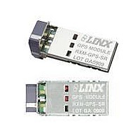
GPS MODULE SMD SIRF W/ANT
Manufacturer
Linx Technologies Inc
Series
SRr
Type
GPS Receiver Moduler
Datasheet
1.MDEV-GPS-SR.pdf
(15 pages)
Specifications of RXM-GPS-SR-T
Package / Case
Module
Operating Voltage
3 V to 4.3 V
Operating Current
31 mA
Frequency Range
1575.42 MHz
Interface Type
UART, USB
Operating Temperature Range
- 30 C to + 85 C
Lead Free Status / RoHS Status
Lead free / RoHS Compliant
Features
-
Voltage - Supply
-
Frequency
-
Operating Temperature
-
Applications
-
Sensitivity
-
Memory Size
-
Data Interface
-
Data Rate - Maximum
-
Modulation Or Protocol
-
Antenna Connector
-
Current - Receiving
-
Lead Free Status / Rohs Status
Lead free / RoHS Compliant


Table 1: SR Series Receiver Specifications
Notes:
1. V
Page 2
ELECTRICAL SPECIFICATIONS
Parameter
POWER SUPPLY
Supply Voltage
Supply Current:
Backup Battery Voltage
Backup Battery Current
Output Logic Low Voltage
Output Logic High Voltage
Output Logic Low Current
Output Logic High Current
Input Logic Low Voltage
Input Logic High Voltage
Input Logic Low Current
Input Logic High Current
ENABLE Logic Low Voltage
ENABLE Logic High Voltage
ENABLE Logic Low Current
ENABLE Logic High Current
ENVIRONMENTAL
Operating Temperature Range
Storage Temperature Range
RECEIVER SECTION
Acquisition Time
Position Accuracy
Altitude
Velocity
Chipset
Firmware Version
Frequency
Channels
Update Rate
Protocol Support
Peak
Sleep
Hot Start (Open Sky)
Cold Start
Autonomous
SBAS
CC
= 3.3V
*CAUTION*
This product incorporates numerous static-sensitive components.
Always wear an ESD wrist strap and observe proper ESD handling
procedures when working with this device. Failure to observe this
precaution may result in module damage or failure.
Designation
GSW3.5.0_3.5.00.00-SDK-3EP2.01A
V
V
I
V
V
I
I
I
V
V
V
V
BAT
I
I
CC
BAT
OH
I
I
OL
–
–
CC
OL
OH
IL
IH
IL
IH
IH
IH
IL
IL
SiRF Star III, GSC3f/LPx 7990
L1 1575.42MHz, C/A Code
NMEA 0183 ver 3.0, SiRF Binary
Min.
-0.3
-0.2
-0.2
1Hz
3.0
1.3
2.0
2.1
-10
-10
1.3
-30
-40
20
–
–
–
–
–
–
–
–
–
–
–
–
–
Typical
<0.1
31
10
25
35
–
–
–
–
2
2
–
–
–
–
–
–
–
–
–
–
–
–
–
–
60,000
1,000
Max.
0.73
0.25
Vcc
+85
+85
4.3
6.0
0.8
3.6
49
60
60
10
10
–
–
–
–
–
1
2
–
5
Units
Knots
VDC
VDC
VDC
VDC
VDC
VDC
VDC
VDC
mA
mA
mA
mA
µA
µA
µA
µA
µA
°
°
m
m
S
S
ft
C
C
Notes
–
1
–
–
–
–
–
–
–
–
–
–
–
–
–
–
–
–
–
–
–
–
–
–
–
–
ABSOLUTE MAXIMUM RATINGS
PIN ASSIGNMENTS
Figure 2: SR Series Receiver Pinout (Top View)
PIN DESCRIPTIONS
Pin #
10
1
2
3
4
5
6
7
8
9
Supply Voltage V
Input Battery Backup Voltage
Operating Temperature
Storage Temperature
Soldering Temperature
*NOTE*
damage to the device. Furthermore, extended operation at these maximum
ratings may reduce the life of this device.
VBACKUP
Name I/O
GND
VCC
GND
GND
LED
RX
NC
EN
TX
Exceeding any of the limits of this section may lead to permanent
P
P
O
O
P
P
P
I
I
CC
Backup battery supply voltage. This line must be
LED Indicator (100kΩ internal pull-down)
Enable (active high, internal pull-down)
Serial Data Output (default NMEA)
Serial Data Input (default NMEA)
powered to enable the module.
No Electrical Connection
-30
-40
Description
+225°C for 10 seconds
Supply Voltage
Ground
Ground
Ground
+5.5
+7.0
to
to
+85
+85
VDC
VDC
°C
°C
Page 3
Related parts for RXM-GPS-SR-T
Image
Part Number
Description
Manufacturer
Datasheet
Request
R

Part Number:
Description:
GPS MODULE SMD SIRF
Manufacturer:
Linx Technologies Inc
Datasheet:

Part Number:
Description:
GPS MODULE SMD SIRF W/ANT
Manufacturer:
Linx Technologies Inc
Datasheet:

Part Number:
Description:
GPS MODULE SMD SIRF
Manufacturer:
Linx Technologies Inc
Datasheet:

Part Number:
Description:
HOLDER BATTERY 20MM COIN CR2032
Manufacturer:
Linx Technologies Inc
Datasheet:

Part Number:
Description:
CONN RPSMA BL CRJA-CPV 8.5" COAX
Manufacturer:
Linx Technologies Inc

Part Number:
Description:
CABLE RG174 RPSMA M/F 8.5"
Manufacturer:
Linx Technologies Inc

Part Number:
Description:
CABLE RG174 SMA M/F 8.5"
Manufacturer:
Linx Technologies Inc

Part Number:
Description:
CABLE RPSMA/SMA 8.5"
Manufacturer:
Linx Technologies Inc

Part Number:
Description:
CABLE MALE-NMALE 8' RG-58 RPSMA
Manufacturer:
Linx Technologies Inc

Part Number:
Description:
CABLE RPSMA/SMA 8.5"
Manufacturer:
Linx Technologies Inc

Part Number:
Description:
MODULE USB LOW SPEED
Manufacturer:
Linx Technologies Inc
Datasheet:

Part Number:
Description:
IC TRANSCODER MT BI-DIR 20-SSOP
Manufacturer:
Linx Technologies Inc
Datasheet:

Part Number:
Description:
IC ENCODER LOW SECURITY 8DIP
Manufacturer:
Linx Technologies Inc
Datasheet:

Part Number:
Description:
IC DECODER MS SERIES 20-SSOP
Manufacturer:
Linx Technologies Inc
Datasheet:
Part Number:
Description:
IC ENCODER MS SERIES 20-SSOP
Manufacturer:
Linx Technologies Inc
Datasheet: