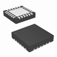
SI4313-B1-FM Silicon Laboratories Inc, SI4313-B1-FM Datasheet - Page 22

SI4313-B1-FM
Manufacturer Part Number
SI4313-B1-FM
Description
IC RX FSK 315-915MHZ 20VQFN
Manufacturer
Silicon Laboratories Inc
Series
EZRadio®r
Type
ISM Receiverr
Specifications of SI4313-B1-FM
Package / Case
20-VQFN
Mfg Application Notes
Si4313 Register Desc AppNote
Frequency
315MHz, 434MHz, 868MHz, 915MHz
Sensitivity
-118dBm
Data Rate - Maximum
128kbps
Modulation Or Protocol
FSK, GFSK, OOK
Applications
Data Logging, Health Monitors, Remote Control, Weather Station
Data Interface
PCB, Surface Mount
Antenna Connector
PCB, Surface Mount
Voltage - Supply
1.8 V ~ 3.6 V
Operating Temperature
-40°C ~ 85°C
Operating Frequency
315 MHz to 915 MHz
Operating Supply Voltage
1.8 V to 3.6 V
Maximum Operating Temperature
+ 85 C
Minimum Operating Temperature
- 40 C
Mounting Style
SMD/SMT
Supply Current
100 nA
Lead Free Status / RoHS Status
Lead free / RoHS Compliant
Features
-
Memory Size
-
Current - Receiving
-
Lead Free Status / Rohs Status
Lead free / RoHS Compliant
Other names
336-1980-5
Available stocks
Company
Part Number
Manufacturer
Quantity
Price
Company:
Part Number:
SI4313-B1-FMR
Manufacturer:
TI
Quantity:
10 000
Part Number:
SI4313-B1-FMR
Manufacturer:
SILICON LABS/芯科
Quantity:
20 000
Si4313-B1
3.4. System Timing
The VCO will automatically calibrate at every frequency change or power-up. The PLL T0 time is to allow for bias
settling of the VCO. The PLL TS time is for the settling time of the PLL, which has a default setting of 100 µs. The
total time for PLL T0, PLL CAL, and PLL TS under all conditions is 200 µs. In certain applications, the PLL T0 time
and the PLL CAL may be skipped for faster turnaround time. Contact applications support if faster turnaround time
is desired.
3.5. Frequency Control
To calculate the necessary frequency register settings, use the Silicon Labs' Wireless Design Suite (WDS) or Excel
Calculator available from the product web page. These methods offer a simple, quick interface to determine the
correct settings based on the application requirement.
3.5.1. Automatic State Transition for Frequency Change
If registers 79h or 7Ah are changed in RX mode, the state machine will automatically transition the chip back to
tune and change the frequency. This feature is useful to reduce the number of SPI commands required in a
Frequency Hopping System. In turn, this reduces microcontroller activity, thereby reducing current consumption.
3.5.2. Frequency Offset Adjustment
When the AFC is disabled, the frequency offset can be adjusted manually by fo[9:0] in registers 73h and 74h. The
frequency offset adjustment and the AFC are both implemented by shifting the Synthesizer Local Oscillator
frequency. This register is a signed register; so, in order to get a negative offset, it is necessary to take the twos
22
Add
75
76
77
R/W
R/W
R/W
R/W
Frequency Band Select
Nominal Carrier Fre-
Nominal Carrier Fre-
Function/Description
quency 1
quency 0
fc[15]
fc[7]
D7
Figure 7. RX Timing
fc[14]
sbsel
fc[6]
D6
Rev. 1.0
hbsel
fc[13]
fc[5]
D5
fc[12]
fb[4]
fc[4]
D4
Data
fc[11]
fb[3]
fc[3]
D3
fc[10]
fb[2]
fc[2]
D2
fb[1]
fc[9]
fc[1]
D1
fb[0]
fc[8]
fc[0]
D0
Default
POR
BBh
35h
80h


