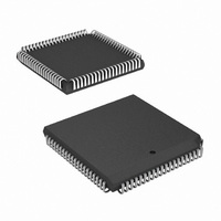
HSP50210JI-52Z Intersil, HSP50210JI-52Z Datasheet - Page 48

HSP50210JI-52Z
Manufacturer Part Number
HSP50210JI-52Z
Description
IC DEMODULATOR COSTAS 84-PLCC
Manufacturer
Intersil
Datasheet
1.HSP50210JC-52Z.pdf
(51 pages)
Specifications of HSP50210JI-52Z
Function
Demodulator
Frequency
52MHz
Rf Type
AM, FM
Package / Case
84-PLCC
Lead Free Status / RoHS Status
Lead free / RoHS Compliant
Available stocks
Company
Part Number
Manufacturer
Quantity
Price
Part Number:
HSP50210JI-52Z
Manufacturer:
INTERSIL
Quantity:
20 000
Absolute Maximum Ratings
Supply Voltage . . . . . . . . . . . . . . . . . . . . . . . . . . . . . . . . . . . . +7.0V
Input, Output Voltage . . . . . . . . . . . . . . . . . GND -0.5V to V
ESD . . . . . . . . . . . . . . . . . . . . . . . . . . . . . . . . . . . . . . . . . . . . Class 3
Operating Conditions
Voltage Range . . . . . . . . . . . . . . . . . . . . . . . . . . . . +4.75V to +5.25V
Temperature Range
CAUTION: Do not operate at or near the maximum ratings listed for extended periods of time. Exposure to such conditions may adversely impact product reliability and
result in failures not covered by warranty.
NOTE:
DC Electrical Specifications
NOTES:
Electrical Specifications
10. Not tested, but characterized at initial design and at major process/design changes.
Power Supply Current
Standby Power Supply Current
Input Leakage Current
Output Leakage Current
Clock Input High
Clock Input Low
Logical One Input Voltage
Logical Zero Input Voltage
Logical One Output Voltage
Logical Zero Output Voltage
Input Capacitance
Output Capacitance
CLK Period
CLK High
CLK Low
SERCLK High
SERCLK Low
7. θ
8. Power supply current is proportional to frequency. Typical rating is 4mA/MHz.
9. Output load per test circuit and C
HSP50210JC (Commercial) . . . . . . . . . . . . . . . . . . . 0°C to +70°C
HSP50210JI (Industrial) . . . . . . . . . . . . . . . . . . . . .-40°C to +85°C
Tech Brief TB379.
JA
is measured in free air with the component mounted on a high effective thermal conductivity test board with “direct attach” features. See
PARAMETER
PARAMETER
48
V
MIN and/or MAX limits are 100% tested at +25°C, unless otherwise specified. Temperature limits
established by characterization and are not production tested.
CC
L
= 40pF.
= 5.0V ±5%, T
V
MIN and/or MAX limits are 100% tested at +25°C, unless otherwise specified. Temperature limits
established by characterization and are not production tested.
CC
= 5.0V ±5%, T
SYMBOL
I
I
C
CCOP
CCSB
V
V
V
V
C
V
V
OUT
I
IHC
ILC
OH
I
OL
O
IH
IN
IL
I
A
= 0°C to +70°C (Commercial), T
CC
A
V
(Notes 8, 9)
V
V
V
V
V
V
V
I
I
f
All measurements referenced to GND.
T
+0.5V
= 0
OH
OL
CLK
A
CC
CC
CC
CC
CC
CC
CC
CC
= +25°C (Note 10)
HSP50210
°
= 2mA, V
= -400µA, V
C to +70
= Max, CLK = 52.6MHz
= Max, Outputs Not Loaded
= Max, Input = 0V or V
= Max, Input = 0V or V
= Max, CLK
= Min, CLK
= Max
= Min
= SCLK = 1MHz
SYMBOL
TEST CONDITIONS
t
t
t
t
t
CP
CH
SH
CC
CL
°
SL
C (Commercial), T
CC
Thermal Information
Thermal Resistance (Typical, Note 7)
Maximum Storage Temperature. . . . . . . . . . . . . . . .-65°C to +150°C
Maximum Junction Temperature PLCC . . . . . . . . . . . . . . . . . +150°C
Pb-Free Reflow Profile. . . . . . . . . . . . . . . . . . . . . . . . .see link below
Die Characteristics
Gate Count . . . . . . . . . . . . . . . . . . . . . . . . . . . . . . . . . . . . . . 45,000
= Min
PLCC Package. . . . . . . . . . . . . . . . . . . . . . . . . . . . .
http://www.intersil.com/pbfree/Pb-FreeReflow.asp
= Min
A
= -40°C to +85°C (Industrial), (Note 11) Parameters with
CC
CC
MIN
19
A
7
7
7
7
= -40
52MHz
°
C to +85
MIN
°
-10
-10
3.0
2.0
2.6
C (Industrial). Parameters with
MAX
-
-
-
-
-
-
-
-
-
-
-
-
MAX
225
500
0.8
0.8
0.4
10
10
10
10
-
-
-
UNITS
ns
ns
ns
ns
ns
θ
UNITS
July 2, 2008
JA
mA
µA
µA
µA
pF
pF
FN3652.5
24
V
V
V
V
V
V
°C/W


