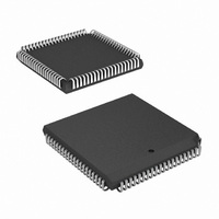
HSP50210JI-52Z Intersil, HSP50210JI-52Z Datasheet - Page 25

HSP50210JI-52Z
Manufacturer Part Number
HSP50210JI-52Z
Description
IC DEMODULATOR COSTAS 84-PLCC
Manufacturer
Intersil
Datasheet
1.HSP50210JC-52Z.pdf
(51 pages)
Specifications of HSP50210JI-52Z
Function
Demodulator
Frequency
52MHz
Rf Type
AM, FM
Package / Case
84-PLCC
Lead Free Status / RoHS Status
Lead free / RoHS Compliant
Available stocks
Company
Part Number
Manufacturer
Quantity
Price
Part Number:
HSP50210JI-52Z
Manufacturer:
INTERSIL
Quantity:
20 000
Search. The frequency uncertainty is swept by enabling the
Frequency Sweep Block to the lag path of the Carrier
Tracking Loop Filter. The acquisition parameters are
enabled to the Loop Filters and the Lock Detector
Accumulators. Phase lock is obtained when the Lock
Counter rolls over before the Phase Error Accumulator
(average Phase Error is less than the lock threshold).
Verify. Once phase lock is obtained, the frequency sweep is
disabled and the tracking parameters are enabled. Lock is
verified if the accumulated Phase Error is below the
threshold for a programmable number of Integration Periods.
False lock conditions are also monitored by comparing the
roll over of the False Lock Accumulator to that of the
Integration Counter. If the False Lock Accumulator rolls over
before the Integration Counter, a false lock condition exists.
False Lock. Once a false lock has been determined, the
Frequency Sweep block is enabled to move the carrier
tracking beyond the false lock region. The Frequency Sweep
is performed for a programmable number of Integration
Periods before returning to the search state.
Lock. When phase lock has been verified, the Lock status
output is asserted and the False Lock Detector is disabled.
DWELL
COUNT
ACQ
COUNTER
DWELL
TC
MUX
SWEPT
TRACK
“0”
START
PERIOD
ACQ
INTEGRATION
INT
COUNTER
MUX
25
TC
PERIOD
TRACK
INT
PRELOAD
ERROR
PHASE
ACQ
FIGURE 17. LOCK DETECTOR BLOCK DIAGRAM
MUX
PRELOAD
ERROR
PHASE
TRACK
LOCK DETECTOR STATE MACHINE
HSP50210
PHASE
ERROR
REG
|X|
+
OVERFLOW
ACQUIRE/
TRACK
PRELOAD
FALSE
LOCK
ACQ
The lock state is maintained as long as the Integration
Counter rolls over before the Phase Error Accumulator.
If the acquisition and tracking process is controlled externally,
the Phase Error Accumulator and False Lock Accumulators
are monitored by an external processor to determine when
lock has been achieved. In this mode the accumulator
pre-loads are typically set to zero and the accumulator output
is compared in the processor against a threshold equal to the
maximum Phase Error per sample times the number of
samples per Integration Period. The accumulators stop after
each Integration Period to hold their outputs for reading via
the Microprocessor Interface (see Read Enable Address Map;
Table 13 on page 28). The accumulators are restarted by
writing the Initialize Lock Detector Control address (see
Initialize Lock Detector Control Register: Table 45 on
page 46). To simplify the processor interface, the LKINT
output is provided to interrupt the processor when the
accumulator integration period is complete. The processor
controls the use of the acquisition/tracking parameters and
lock status line by setting the appropriate bits in the
Acquisition/Tracking Configuration Control Register (see
Table 38 on page 41). In addition, the frequency sweep
function is enabled via the Microprocessor Interface.
MUX
PRELOAD
TRACK
FALSE
LOCK
FALSE LOCK/
FREQUENCY
ERROR
REG
|X|
+
OVERFLOW
“0”
ERROR
GAIN
|X|
REG
+
July 2, 2008
FN3652.5


