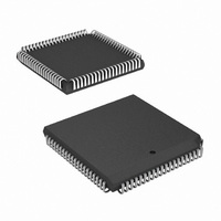
HSP50210JI-52Z Intersil, HSP50210JI-52Z Datasheet - Page 42

HSP50210JI-52Z
Manufacturer Part Number
HSP50210JI-52Z
Description
IC DEMODULATOR COSTAS 84-PLCC
Manufacturer
Intersil
Datasheet
1.HSP50210JC-52Z.pdf
(51 pages)
Specifications of HSP50210JI-52Z
Function
Demodulator
Frequency
52MHz
Rf Type
AM, FM
Package / Case
84-PLCC
Lead Free Status / RoHS Status
Lead free / RoHS Compliant
Available stocks
Company
Part Number
Manufacturer
Quantity
Price
Part Number:
HSP50210JI-52Z
Manufacturer:
INTERSIL
Quantity:
20 000
POSITION
POSITION
POSITION
POSITION
31-16
15-13
31-8
BIT
N/A
BIT
N/A
BIT
BIT
6-0
12
11
7
Stop Lock Detector for
Reading
Restart Lock Detector
Not Used
Slicer Output Format
Soft Decision
Threshold
Not Used
Reserved
Serial Data Sync
Polarity
(SOF output)
Serial Data Sync
Polarity
(COF output)
FUNCTION
FUNCTION
FUNCTION
FUNCTION
TABLE 41. SOFT DECISION SLICER CONFIGURATION CONTROL REGISTER
42
TABLE 39. HALT LOCK DETECTOR FOR READING CONTROL REGISTER
TABLE 42. SERIAL OUTPUT CONFIGURATION CONTROL REGISTER
TABLE 40. RESTART LOCK DETECTOR CONTROL REGISTER
Writing this location halts the Lock Detector State Machine at the end of the current Lock Detector
Accumulator integration cycle. This function is provided so that the Lock Detector integrators can be
stopped for reading via the microprocessor interface (only useful when the Lock Detector is under
internal state machine control). Bit 7 of the internal status register can be monitored via the
Microprocessor Interface to determine when the Lock Detector has stopped and is ready for reading.
See Table 14 for information on the internal status bits. The Lock Detector will remain stopped until
restarted (see Restart Lock Detector Control Register: Table 40).
Writing this location restarts the Lock Detector State Machine following a read of the Lock Detector. Note:
Stopping the Lock Detector for reading is not required in Microprocessor Control Mode since the Lock
Detector Accumulators stop at the end of each integration cycle. See also Table 45.
No programming required.
0 = Soft decision outputs are in sign/magnitude format.
1 = Soft decision outputs are in two’s complement format.
The input to the slicer is compared against thresholds which are 1x, 2x and 3x the value programmed
here. The slicer output depends on the relationship of the I or Q magnitude to the 3 soft thresholds as
given in Table 9. The threshold is programmed as a fractional unsigned value with the following bit
weightings:
0. 2
Note: Since the signal magnitude on either the I or Q path ranges between 0.0 and
value should not exceed 1.0/3 = 0.33. Bit position 6 is the MSB.
No programming required.
Set to zero for proper operation.
0 = SOFSYNC pulses “High” one serial clock before data word on SOF.
1 = SOFSYNC pulses “Low” one serial clock before data word on SOF.
Set to 0 for use with the HSP50110.
0 = COFSYNC pulses “High” one serial clock before data word on COF.
1 = COFSYNC pulses “Low” one serial clock before data word on COF.
Set to 0 for use with the HSP50110.
-1
2
-2
2
-3
2
-4
DESTINATION ADDRESS = 24
DESTINATION ADDRESS = 25
DESTINATION ADDRESS = 26
DESTINATION ADDRESS = 27
2
-5
2
-6
HSP50210
2
-7
.
DESCRIPTION
DESCRIPTION
DESCRIPTION
DESCRIPTION
~
1.0, the threshold
July 2, 2008
FN3652.5


