DR-TRC103-915-DK RFM, DR-TRC103-915-DK Datasheet - Page 15
DR-TRC103-915-DK
Manufacturer Part Number
DR-TRC103-915-DK
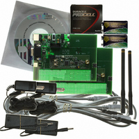
Description
RFIC TRANCEIVER DEVELOPMENT KIT
Manufacturer
RFM
Type
Transceiver, SRRr
Datasheets
1.DR-TRC103-868-DK.pdf
(1 pages)
2.DR-TRC103-868-DK.pdf
(22 pages)
3.DR-TRC103-868-DK.pdf
(6 pages)
Specifications of DR-TRC103-915-DK
Frequency
902MHz ~ 928MHz
For Use With/related Products
TRC103-915
Lead Free Status / RoHS Status
Lead free / RoHS Compliant
Other names
583-1057


The firmware includes several command formats that are used by the RFIC Design
Assistant utility program to read and write parameters to the TRC103 configuration
registers and to send and receive terminal mode messages. Table 6 summarizes
several commands that are useful for proof-of-concept testing.
Command
Write Register
Terminal Mode Send
Terminal Mode Receive
Custom Firmware Development Support
The 10-pin programming header on the interface board is compatible with the Silicon
Labs development tools for the C8051F310 microcontroller. This allows the user to
develop and test custom firmware for use with the TRC103.
www.RFM.com
©2009-2010 by RF Monolithics, Inc.
Figure 16 - DR-TRC103/105 Interface Board Connector for Firmware Development Support
Table 6 - DR-TRC103 Firmware Serial Commands
02msg030D0A
02msg03
Format
Wrrdd
wrrdd
or
Technical support +1.800.704.6079
E-mail:
Write register rr with data dd, where rr and dd are two
character hex values. For example, write 0x80 to register
0x01 is formatted as W0108.
The DR-TRC103 radio board must be in terminal mode, as
discussed in Table 5 above. The user’s message, up to 63
bytes, must be preceded with an ASCII 0x02 start-of-text
character, and followed by an ASCII 0x03 end-of-text
character. For example, the string of hex characters to
send Hello in ASCII is: 0248656C6C6F03
When the example string above is output by the receiving
node, an ASCII carriage return - line feed is added as
follows: 0248656C6C6F030D0A
info@rfm.com
Example
DR-TRC103-DK - 04/05/10
Page 15 of 22
Related parts for DR-TRC103-915-DK
Image
Part Number
Description
Manufacturer
Datasheet
Request
R

Part Number:
Description:
RFIC TRANCEIVER DEVELOPMENT KIT
Manufacturer:
RFM
Datasheet:

Part Number:
Description:
ASH RX 115.2 KBPS 433.92 MHZ
Manufacturer:
RFM
Datasheet:

Part Number:
Description:
RFIC TRANCEIVER MULTI-CHANNEL FS
Manufacturer:
RFM
Datasheet:

Part Number:
Description:
ASH TX 115.2 KBPS 433.92 MHZ
Manufacturer:
RFM
Datasheet:
Part Number:
Description:
Filters 1602MHz BW=61MHz
Manufacturer:
RFM
Datasheet:

Part Number:
Description:
RESONATOR, SM3030-6
Manufacturer:
RFM
Datasheet:

Part Number:
Description:
RESONATOR, SM3030-6
Manufacturer:
RFM
Datasheet:

Part Number:
Description:
RESONATOR, SM3030-6
Manufacturer:
RFM
Datasheet:

Part Number:
Description:
RESONATOR, SM5035-4
Manufacturer:
RFM
Datasheet:
Part Number:
Description:
RESONATOR 418MHZ SM5035-4
Manufacturer:
RFM
Datasheet:
Part Number:
Description:
WiFi / 802.11 Modules 2.4 and 5.8GHz + BT
Manufacturer:
RFM
Datasheet:

Part Number:
Description:
10-Terminal Ceramic Surface-Mount Case 7 x 5 mm Nominal Footprint
Manufacturer:
RFM [RF Monolithics, Inc]
Datasheet:
Part Number:
Description:
QUAD-BAND GSM850/GSM/DCS/PCS POWER AMP MODULE
Manufacturer:
RFM [RF Monolithics, Inc]
Datasheet:
Part Number:
Description:
402 to 405 MHz Medical Band Front-end Filter
Manufacturer:
RFM [RF Monolithics, Inc]
Datasheet: