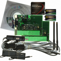
DR-TRC103-915-DK RFM, DR-TRC103-915-DK Datasheet - Page 13

DR-TRC103-915-DK
Manufacturer Part Number
DR-TRC103-915-DK
Description
RFIC TRANCEIVER DEVELOPMENT KIT
Manufacturer
RFM
Type
Transceiver, SRRr
Datasheets
1.DR-TRC103-868-DK.pdf
(1 pages)
2.DR-TRC103-868-DK.pdf
(22 pages)
3.DR-TRC103-868-DK.pdf
(6 pages)
Specifications of DR-TRC103-915-DK
Frequency
902MHz ~ 928MHz
For Use With/related Products
TRC103-915
Lead Free Status / RoHS Status
Lead free / RoHS Compliant
Other names
583-1057
Interface Board Details
Figure 14 and Table 4 summarizes the functions of the DR-TRC103/105 interface board
connectors, user controls and LED indicators. Also note that many of the radio board
test points are duplicated on the edge of the interface board prototyping area.
Component
Radio Connector
Micro Connector
RS232 Connector
Power Connector
Power Input Pins
USB Connector
Battery Connectors
Serial Monitor Pins
TX Serial Jumper
RX Serial Jumper
POWER Switch
Radio RESET Switch
POWER LED
USB ON LED
www.RFM.com
©2009-2010 by RF Monolithics, Inc.
Table 4 - DR-TRC103/105 Interface Board Connector, Control and Indicator Functions
Designator
Figure 14 - DR-TRC103/105 Interface Board Details
J7-J8
SW1
SW2
J10
J11
D1
D2
J1
J2
J4
J5
J6
J9
J3
Technical support +1.800.704.6079
20-pin radio board interface connector
10-pin microprocessor programming connector, SiLabs compatible
RS232 9-pin D connector
Coaxial power connector, 4.5 to 12 volts
Alternate power input pins, 4.5 to 12 volts
Type B USB Connector
9 volt battery connectors
Monitoring pins for logic-level serial data
Routes logic-level serial data to USB converter, remove for
RS232 operation
Routes logic-level serial data from USB converter, remove for
RS232 operation
Regulated 3 volt power switch
Radio firmware reset switch
Green LED illuminates when POWER switch is on
Green LED illuminates when USB is active
E-mail:
info@rfm.com
Function
DR-TRC103-DK - 04/05/10
Page 13 of 22


