DR-TRC103-915-DK RFM, DR-TRC103-915-DK Datasheet - Page 14
DR-TRC103-915-DK
Manufacturer Part Number
DR-TRC103-915-DK
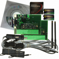
Description
RFIC TRANCEIVER DEVELOPMENT KIT
Manufacturer
RFM
Type
Transceiver, SRRr
Datasheets
1.DR-TRC103-868-DK.pdf
(1 pages)
2.DR-TRC103-868-DK.pdf
(22 pages)
3.DR-TRC103-868-DK.pdf
(6 pages)
Specifications of DR-TRC103-915-DK
Frequency
902MHz ~ 928MHz
For Use With/related Products
TRC103-915
Lead Free Status / RoHS Status
Lead free / RoHS Compliant
Other names
583-1057


Radio Board Firmware Details
Table 5 summarizes the switch-selectable modes supported by the radio board
firmware. Figure 15 shows the location of the mode selection switches and LEDs.
www.RFM.com
©2009-2010 by RF Monolithics, Inc.
Mode
Reset
Receive Continuous
Transmit Continuous
Sleep Cycle
Range Test Receive
(Packet Receive)
Range Test Transmit
Terminal
RESET
Table 5 - DR-TRC103 Firmware Switch-selectable Modes
Cycle power or press the RESET switch on the interface board. All LEDs
on the radio board will flash, and the MODE LED will illuminate green. The
default operating frequency and firmware version message is output on the
serial connection.
Default mode following a reset. MODE LED is green.
Following a reset, press the MODE button briefly. MODE LED is yellow.
Following a reset, press the MODE button twice briefly. MODE LED is off.
Serial/PLL LED will periodically flash.
Following a reset, press the RANGE button briefly. The RANGE LED will
illuminate yellow. The message RX MODE is output on the serial
connection.
Following a reset, press and hold the RANGE button until several LEDs
begin flashing.
Following a reset, press the RANGE button briefly twice, with about one
second between the first and second button press. On the first press, the
The message RX MODE is output on the serial connection. On the second
button press, the message TERM MODE is output on the serial connection.
Figure 15 - Mode Switches and LEDs
Technical support +1.800.704.6079
E-mail:
info@rfm.com
Mode Selection
DR-TRC103-DK - 04/05/10
Page 14 of 22
Related parts for DR-TRC103-915-DK
Image
Part Number
Description
Manufacturer
Datasheet
Request
R

Part Number:
Description:
RFIC TRANCEIVER DEVELOPMENT KIT
Manufacturer:
RFM
Datasheet:

Part Number:
Description:
ASH RX 115.2 KBPS 433.92 MHZ
Manufacturer:
RFM
Datasheet:

Part Number:
Description:
RFIC TRANCEIVER MULTI-CHANNEL FS
Manufacturer:
RFM
Datasheet:

Part Number:
Description:
ASH TX 115.2 KBPS 433.92 MHZ
Manufacturer:
RFM
Datasheet:
Part Number:
Description:
Filters 1602MHz BW=61MHz
Manufacturer:
RFM
Datasheet:

Part Number:
Description:
RESONATOR, SM3030-6
Manufacturer:
RFM
Datasheet:

Part Number:
Description:
RESONATOR, SM3030-6
Manufacturer:
RFM
Datasheet:

Part Number:
Description:
RESONATOR, SM3030-6
Manufacturer:
RFM
Datasheet:

Part Number:
Description:
RESONATOR, SM5035-4
Manufacturer:
RFM
Datasheet:
Part Number:
Description:
RESONATOR 418MHZ SM5035-4
Manufacturer:
RFM
Datasheet:
Part Number:
Description:
WiFi / 802.11 Modules 2.4 and 5.8GHz + BT
Manufacturer:
RFM
Datasheet:

Part Number:
Description:
10-Terminal Ceramic Surface-Mount Case 7 x 5 mm Nominal Footprint
Manufacturer:
RFM [RF Monolithics, Inc]
Datasheet:
Part Number:
Description:
QUAD-BAND GSM850/GSM/DCS/PCS POWER AMP MODULE
Manufacturer:
RFM [RF Monolithics, Inc]
Datasheet:
Part Number:
Description:
402 to 405 MHz Medical Band Front-end Filter
Manufacturer:
RFM [RF Monolithics, Inc]
Datasheet: