1320X-QE-DSK-BDM Freescale Semiconductor, 1320X-QE-DSK-BDM Datasheet - Page 38
1320X-QE-DSK-BDM
Manufacturer Part Number
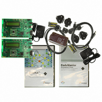
1320X-QE-DSK-BDM
Description
KIT EVAL FOR MC1320X BDM CABLE
Manufacturer
Freescale Semiconductor
Type
Transceiver, 802.15.4/ZigBeer
Specifications of 1320X-QE-DSK-BDM
Frequency
2.4GHz
Interface Type
USB
For Use With/related Products
MC1320x
Lead Free Status / RoHS Status
Lead free / RoHS Compliant


PCB Manufacturing Specifications
6.2
The panel size can be negotiated depending on production volume.
6-2
•
•
Solder mask is required
Silk screen is required
Layer
Panelization
1
2
3
4
5
6
The 1320x-QE128EVB contains high frequency 2.4 GHz RF circuitry. As a
result , RF component placement, line geometries and layout, and spacing
to the ground plane are critical parameters. As a result, BOARD STACKUP
GEOMETRY IS CRITICAL. Dielectric and copper thicknesses and spacing
must not be changed; follow the stackup (see
provided with the reference design.
Solder Resist
Copper Top Layer (component side; layer 1)
Copper 2nd Layer
Copper 3nd Layer
Copper bottom Layer
Solder Resist
Artwork Identification
1320x-QE128EVB Reference Manual, Rev. 1.0
Figure 6-1. PCB Stackup Cross-Section
Table 6-1. Layer by Layer Overview
Dielectric
Dielectric
Dielectric
NOTE
Figure
SMtop.art / SMtop.pdf
TOP.art /TOP.pdf
GND.art / GND.pdf
INS.art / INS.pdf
BOT.art /BOT.pdf
SMbot.art / SMbot.pdf
6-1) information is
Metal 4
Metal 3
Metal 2
Metal 1
File Name
Freescale Semiconductor
Related parts for 1320X-QE-DSK-BDM
Image
Part Number
Description
Manufacturer
Datasheet
Request
R

Part Number:
Description:
KIT DEV FOR MC1320X QE RFIC
Manufacturer:
Freescale Semiconductor
Datasheet:

Part Number:
Description:
Manufacturer:
Freescale Semiconductor, Inc
Datasheet:
Part Number:
Description:
Manufacturer:
Freescale Semiconductor, Inc
Datasheet:
Part Number:
Description:
Manufacturer:
Freescale Semiconductor, Inc
Datasheet:
Part Number:
Description:
Manufacturer:
Freescale Semiconductor, Inc
Datasheet:
Part Number:
Description:
Manufacturer:
Freescale Semiconductor, Inc
Datasheet:
Part Number:
Description:
Manufacturer:
Freescale Semiconductor, Inc
Datasheet:
Part Number:
Description:
Manufacturer:
Freescale Semiconductor, Inc
Datasheet:
Part Number:
Description:
Manufacturer:
Freescale Semiconductor, Inc
Datasheet:
Part Number:
Description:
Manufacturer:
Freescale Semiconductor, Inc
Datasheet:
Part Number:
Description:
Manufacturer:
Freescale Semiconductor, Inc
Datasheet:
Part Number:
Description:
Manufacturer:
Freescale Semiconductor, Inc
Datasheet:
Part Number:
Description:
Manufacturer:
Freescale Semiconductor, Inc
Datasheet:
Part Number:
Description:
Manufacturer:
Freescale Semiconductor, Inc
Datasheet:
Part Number:
Description:
Manufacturer:
Freescale Semiconductor, Inc
Datasheet: