1320X-QE-DSK-BDM Freescale Semiconductor, 1320X-QE-DSK-BDM Datasheet - Page 27
1320X-QE-DSK-BDM
Manufacturer Part Number
1320X-QE-DSK-BDM
Description
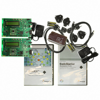
KIT EVAL FOR MC1320X BDM CABLE
Manufacturer
Freescale Semiconductor
Type
Transceiver, 802.15.4/ZigBeer
Specifications of 1320X-QE-DSK-BDM
Frequency
2.4GHz
Interface Type
USB
For Use With/related Products
MC1320x
Lead Free Status / RoHS Status
Lead free / RoHS Compliant


4.11
Table 4-6
board include:
Freescale Semiconductor
Jumper
J13
J15
J1
J5
J6
•
•
•
•
•
J1 - used to measure current and voltage on V_RF
J5 - used to select clock input to the MCU either from the MC1320x CLKO output or from an
optional on-board (Y2) 32.768KHz crystal.
J6 - used to measure current and voltage on V_BB
J13 - used to connect MCU TxD1 pin to the on-board RS-232 transceiver (U5)
J15 - used to connect MCU RxD1 pin to the on-board RS-232 transceiver (U5)
Pin Number
Connection
Jumper Selection
lists all the possible jumper selections for the 1320x-QE128EVB. The jumpers available on the
1-2
1-2
1-2
2-3
1-2
1-2
Provide the means for voltage and current measurements on the MC1320x Transceiver
Connects MCU QE128 XTAL with MC1320x CLKO output
Connects MCU QE128 XTAL with on-board 32.768KHz crystal
Provide the means for voltage and current measurements on the MCU QE128
Provide the means to connect the on-board RS-232 transceiver with MCU TXD1
Provide the means to connect the on-board RS-232 Transceiver with MCU RXD1
Number
Pin
27
28
29
30
31
32
Table 4-5. GPIO Connector J4 Pinouts (continued)
PTE0
GND
NC
GND
NC
GND
1320x-QE128EVB Reference Manual, Rev. 1.0
Name
Table 4-6. Jumper Selection
Timer/PWM Channel or GPIO
System ground
System ground
System ground
Description
Function
Interface Locations and Pinouts
Mounted
Mounted
Not
Mounted
Mounted
Mounted
Mounted
Default
Setting
4-7
Related parts for 1320X-QE-DSK-BDM
Image
Part Number
Description
Manufacturer
Datasheet
Request
R

Part Number:
Description:
KIT DEV FOR MC1320X QE RFIC
Manufacturer:
Freescale Semiconductor
Datasheet:

Part Number:
Description:
Manufacturer:
Freescale Semiconductor, Inc
Datasheet:
Part Number:
Description:
Manufacturer:
Freescale Semiconductor, Inc
Datasheet:
Part Number:
Description:
Manufacturer:
Freescale Semiconductor, Inc
Datasheet:
Part Number:
Description:
Manufacturer:
Freescale Semiconductor, Inc
Datasheet:
Part Number:
Description:
Manufacturer:
Freescale Semiconductor, Inc
Datasheet:
Part Number:
Description:
Manufacturer:
Freescale Semiconductor, Inc
Datasheet:
Part Number:
Description:
Manufacturer:
Freescale Semiconductor, Inc
Datasheet:
Part Number:
Description:
Manufacturer:
Freescale Semiconductor, Inc
Datasheet:
Part Number:
Description:
Manufacturer:
Freescale Semiconductor, Inc
Datasheet:
Part Number:
Description:
Manufacturer:
Freescale Semiconductor, Inc
Datasheet:
Part Number:
Description:
Manufacturer:
Freescale Semiconductor, Inc
Datasheet:
Part Number:
Description:
Manufacturer:
Freescale Semiconductor, Inc
Datasheet:
Part Number:
Description:
Manufacturer:
Freescale Semiconductor, Inc
Datasheet:
Part Number:
Description:
Manufacturer:
Freescale Semiconductor, Inc
Datasheet: