1320X-QE-DSK-BDM Freescale Semiconductor, 1320X-QE-DSK-BDM Datasheet - Page 23
1320X-QE-DSK-BDM
Manufacturer Part Number
1320X-QE-DSK-BDM
Description
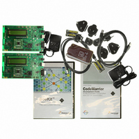
KIT EVAL FOR MC1320X BDM CABLE
Manufacturer
Freescale Semiconductor
Type
Transceiver, 802.15.4/ZigBeer
Specifications of 1320X-QE-DSK-BDM
Frequency
2.4GHz
Interface Type
USB
For Use With/related Products
MC1320x
Lead Free Status / RoHS Status
Lead free / RoHS Compliant


4.2.4
It is possible to isolate various circuit blocks to measure current draw via 0-ohm resistors. The resistors
are all mounted as default.
Below is a list of the supply nodes.
4.3
The MC9S08QE128 MCU is provided as a module that mounts as a daughter card on the main PBC. Four
2x8 headers designated J7, J8, J10, and J11 are used to mount the module.
4.4
The 1320x-QE128EVB RF circuitry contains a printed metal F-antenna (ANT1).
4.5
The USB connector is a “B”-type device and is designated as J12.
The USB port is connected to MCU port SCI2.
4.6
The LCD module is connected to the main circuit board via one of two 16-pin connectors (either J16 or
J17). Each connector supports a different LCD module format. The default LCD designated as the
CFAH1602B device uses the J17 connector.
Freescale Semiconductor
•
•
•
•
•
•
•
R8 -> V_RS232 (Supply for RS-232 Transceiver circuit)
R6 -> V_PERIF (Output from on-board regulator for GPIO customer access)
R5 -> V_LCD (Supply for LCD Daughter Board)
R21 -> V_BB (Supply for QE128 EVB)
R20 -> V_RF (Supply for MC1320x)
R3 -> V_LED (Supply for LEDs)
R2 -> VCC (Output from main on-board regulator)
MC9S08QE128 MCU Module
RF Circuitry
USB Connector (“B” Receptacle)
LCD Connector
Power Measurement
The MCU is mounted to the module during manufacturing. Freescale
recommends that users do not remove and replace this module.
1320x-QE128EVB Reference Manual, Rev. 1.0
Figure 4-2. USB Connector Pinout
NOTE
Figure 4-2
shows the connector pinout.
Interface Locations and Pinouts
4-3
Related parts for 1320X-QE-DSK-BDM
Image
Part Number
Description
Manufacturer
Datasheet
Request
R

Part Number:
Description:
KIT DEV FOR MC1320X QE RFIC
Manufacturer:
Freescale Semiconductor
Datasheet:

Part Number:
Description:
Manufacturer:
Freescale Semiconductor, Inc
Datasheet:
Part Number:
Description:
Manufacturer:
Freescale Semiconductor, Inc
Datasheet:
Part Number:
Description:
Manufacturer:
Freescale Semiconductor, Inc
Datasheet:
Part Number:
Description:
Manufacturer:
Freescale Semiconductor, Inc
Datasheet:
Part Number:
Description:
Manufacturer:
Freescale Semiconductor, Inc
Datasheet:
Part Number:
Description:
Manufacturer:
Freescale Semiconductor, Inc
Datasheet:
Part Number:
Description:
Manufacturer:
Freescale Semiconductor, Inc
Datasheet:
Part Number:
Description:
Manufacturer:
Freescale Semiconductor, Inc
Datasheet:
Part Number:
Description:
Manufacturer:
Freescale Semiconductor, Inc
Datasheet:
Part Number:
Description:
Manufacturer:
Freescale Semiconductor, Inc
Datasheet:
Part Number:
Description:
Manufacturer:
Freescale Semiconductor, Inc
Datasheet:
Part Number:
Description:
Manufacturer:
Freescale Semiconductor, Inc
Datasheet:
Part Number:
Description:
Manufacturer:
Freescale Semiconductor, Inc
Datasheet:
Part Number:
Description:
Manufacturer:
Freescale Semiconductor, Inc
Datasheet: