JN5148-EK010 Jennic LTD, JN5148-EK010 Datasheet - Page 21
JN5148-EK010
Manufacturer Part Number
JN5148-EK010
Description
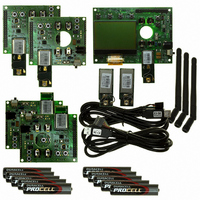
KIT EVAL ZIGBEE PRO JN5148
Manufacturer
Jennic LTD
Series
JN5148r
Type
Transceiverr
Specifications of JN5148-EK010
Frequency
2.4GHz
Silicon Manufacturer
Jennic
Silicon Core Number
JN5148
Kit Contents
SDK, User Guides, Reference Manual
Silicon Family Name
Zigbee PRO
Features
Rapid Application Development And Demonstration
Lead Free Status / RoHS Status
Lead free / RoHS Compliant
For Use With/related Products
ZigBee Pro
Lead Free Status / RoHS Status
Lead free / RoHS Compliant, Lead free / RoHS Compliant
Other names
616-1044
935294044596
JN5148-EK010
935294044596
JN5148-EK010


JN-UG-3062 v2.1
Step 4 Select the radio channel for the network (optional)
Step 5 Start the demonstration on the Controller board
Step 6 Start the Sensor boards
The power LED will be illuminated and the Start-up screen will appear on the LCD
screen. In addition, text labels for the four buttons SW1-SW4 will appear along the
lower edge of the screen.
If you do not want to operate the network in the default channel for the demonstration
(which is 2400-MHz channel 18), you can use the two middle buttons (SW2 and SW3)
on the Controller board to increase and decrease the channel number.
Run the demonstration on the Controller board by pressing the button labelled ‘Done’
on the far right (SW4). The four LEDs D1-D4 will be illuminated.
As the Co-ordinator, this board will create the new wireless network. As part of the
network creation process, the Co-ordinator will set the channel to be used by the
network according to the selection made in Step 4.
Once the node has started and its sensor measurements are being used, LED D1 is
extinguished.
Power on each of three Sensor boards using the slide-switch SW6 on the side of the
board. You can use any three Sensor boards. You are advised to power on the
Router(s) first (the Sensor boards with SMA-connected antennae).
As each Sensor board powers up, LED D9 on the board will be illuminated.
The Routers and End Devices will then search for the network and join it. As each
board joins the network, one of the LEDs D1-D4 on the Controller board is
extinguished and the Sensor board is assigned a name which appears on the LCD
screen - the nodes are assigned the names of rooms in the home, in the following
order: Hall, Bedroom, Lounge, Bathroom. On the Sensor board, LED D1 will flash to
indicate that the board is a member of the network and LED D2 will flash every time
the board transmits sensor data.
By default, the temperature measurement from each node will be displayed on the
screen - this is the ‘Temperature’ screen of the Controller board application’s user
interface (see the photograph below).
© NXP Laboratories UK 2010
JN5148-EK010 Evaluation Kit
User Guide
21
Related parts for JN5148-EK010
Image
Part Number
Description
Manufacturer
Datasheet
Request
R

Part Number:
Description:
KIT UPGRADE ZIGBEE PRO
Manufacturer:
Jennic LTD
Datasheet:

Part Number:
Description:
32BIT, MCU, ZIGBEE PRO, 128K RAM, 56QFN
Manufacturer:
Jennic LTD
Datasheet:

Part Number:
Description:
MODULE, ZIGBEE PRO, W/INTEGRATED ANT
Manufacturer:
Jennic LTD
Part Number:
Description:
MODULE, ZIGBEE PRO, HI-PWR W/UFL ANT
Manufacturer:
Jennic LTD

Part Number:
Description:
KIT EVAL IEEE802.15.4 JN5139
Manufacturer:
Jennic LTD
Datasheet:

Part Number:
Description:
MODULE ZIGBEE CERM ANT JN5139
Manufacturer:
Jennic LTD
Datasheet:

Part Number:
Description:
32BIT MCU, ZIGBEE, 192K ROM, 5139
Manufacturer:
Jennic LTD
Datasheet:

Part Number:
Description:
ZigBee Module W/ Integrated Antenna
Manufacturer:
Jennic LTD
Datasheet:

Part Number:
Description:
ZigBee Module W/ SMA Connector
Manufacturer:
Jennic LTD
Datasheet:

Part Number:
Description:
ZigBee Extended Range Module W/ SMA Connector
Manufacturer:
Jennic LTD
Datasheet:

Part Number:
Description:
ZigBee Extended Range Module W/ UFI Connector
Manufacturer:
Jennic LTD
Datasheet:
Part Number:
Description:
32BIT MCU, ZIGBEE, 192K ROM, 5139
Manufacturer:
Jennic LTD
Datasheet:
Part Number:
Description:
32BIT, MCU, ZIGBEE PRO, 128K RAM, 56QFN
Manufacturer:
Jennic LTD
Datasheet: